Transcription of Fisher C1 Pneumatic Controllers and Transmitters - …
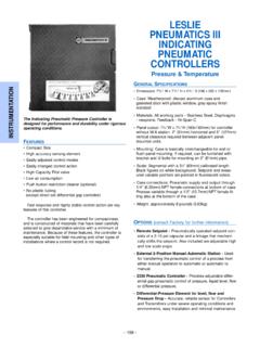
1 C1 Pneumatic Controllers of Adjustment: Set Adjustment: Proportional : Proportional-Only : Proportional-Only Adjustment: Set Adjustment: Proportional Adjustment: Adjustment: Anti-Reset Calibration: Calibration: Anti-Reset : Gap Adjustment: Set Adjustment: Proportional : Differential Gap : Differential Gap : : 1. Fisher C1 controller Yoke-Mounted onControl Valve ActuatorW9263-1 Calibration: : of with Anti-Reset Gap Bourdon Bellows Sensing Proportional or Reset Anti-Reset Windup DifferentialRelief to a DifferentialGap to Direct Output Signal ManualD103292X012C1 Controllers and TransmittersAugust 2018 Instruction ManualD103292X012C1 Controllers and TransmittersAugust 20182 Contents (Continued)Parts Parts for Panel, Wall, Pipestandor Actuator of ManualThis instruction manual provides installation, operating, maintenance, and parts information for the Fisher C1 pressurecontrollers and Transmitters shown in figure 1.
2 Refer to separate instruction manuals for information regarding thecontrol valve, actuator, and not install, operate, or maintain C1 pressure Controllers and Transmitters without first being fully trained andqualified in valve, actuator, and accessory installation, operation, and maintenance. To avoid personal injury andproperty damage, it is important to carefully read, understand, and follow all the contents of this manual, includingall safety cautions and warnings. If you have any questions about these instructions, contact your Emerson sales officeor Local Business Partner before C1 Pneumatic pressure Controllers and Transmitters use a bellows or Bourdon tube sensing element to sense thegauge pressure, vacuum, compound pressure, or differential pressure of a liquid or gas.
3 The controller or transmitteroutput is a Pneumatic pressure signal that can be used to operate a final control element, indicating device, orrecording otherwise noted, all NACE references are to NACE MR0175 / ISO15156 & NACE for the C1 Controllers and Transmitters are listed in table 1. Table 2 explains available configurations ServicesFor information on available courses for C1 Controllers and Transmitters , as well as a variety of other products, contact:Emerson Automation SolutionsEducational Services - RegistrationPhone: +1-641-754-3771 or +1-800-338-8158e-mail: ManualD103292X012C1 Controllers and TransmittersAugust 20183 Table 1.
4 SpecificationsAvailable ConfigurationsSee table 2 Input SignalType: JGauge pressure, Jvacuum, Jcompoundpressure, or Jdifferential pressure of a liquid or gasLimits: See table 3 or 4 Output SignalProportional-Only or Proportional-Plus-ResetControllers and to bar (3 to 15 psig) to bar (6 to 30 psig) Pneumatic pressuresignalDifferential Gap Controllers :J0 and bar (0 and 20 psig) orJ0 and bar (0 and 35 psig) Pneumatic pressuresignalAction: Control action is field reversible betweenJdirect (increasing sensed pressure producesincreasing output signal) and Jreverse (increasingsensed pressure produces decreasing output signal).
5 Supply Pressure Requirements(1)See table 5 Supply Pressure MediumAir or Natural GasSupply medium must be clean, dry and non-corrosivePer ISA Standard maximum 40 micrometer particle size in the airsystem is acceptable. Further filtration down to 5micrometer particle size is recommended. Lubricantcontent is not to exceed 1 ppm weight (w/w) orvolume (v/v) basis. Condensation in the air supplyshould be minimizedPer ISO 8573-1 Maximum particle density size: Class 7 Oil content: Class 3 Pressure Dew Point: Class 3 or at least 10 C less thanthe lowest ambient temperature expectedSteady-State Air Consumption(2)(3) to bar (3 to 15 psig): normal m3/hour (3 scfh) to bar (6 to 30 psig): normal m3/hour ( scfh)Supply and Output Connections1/4 NPT internalCommon Signal Pressure ConversionsSee table 6 Proportional Band AdjustmentFor Proportional-Only Controllers .
6 Full outputpressure change adjustable from J2% to 100% of thesensing element range for to bar (3 to 15 psig)or J4% to 100% of the sensing element range for bar (6 to 30 psig)For Proportional-Plus-Reset Controllers : Full outputpressure change adjustable from J3% to 100% of thesensing element range for to bar (3 to 15psig), or J6% to 100% of the sensing element rangefor to bar (6 to 30 psig)Differential Gap AdjustmentFor Differential Gap Controllers :Full output pressure change adjustable from 15% to 100% of sensing element rangeReset AdjustmentFor Proportional-Plus-Reset Controllers : Adjustablefrom to 74 minutes per repeat (100 to per minute)Zero Adjustment ( Transmitters Only)Continuously adjustable to position span of less than100% anywhere within the sensing element rangeSpan Adjustment ( Transmitters Only)Full output pressure change adjustable from 6 to100% of sensing element rangePerformanceRepeatability.
7 Of sensing element rangeDeadband (Except Differential Gap Controllers )(4) of sensing element rangeTypical Frequency Response at 100% ProportionalBandOutput to Actuator: Hz and 110 degree phase shiftwith 1850 cm3 (113 inches3) volume, actuator atmid-strokeOutput to Positioner Bellows: 9 Hz and 130 degreephase shift with to bar (3 to 15 psig) output to33 cm3 (2 inches3) bellows-continued-Instruction ManualD103292X012C1 Controllers and TransmittersAugust 20184 Table 1. Specifications (continued)Ambient Operating Temperature Limits(1)JStandard Construction: -40 to 71_C (-40 to 160_F)JHigh Temperature Construction.
8 -18 to 104_C (0 to 220_F)Anti-reset windup (differential pressure relief) andprocess pressure gauge options are only available inthe standard constructionIf the process temperature is outside the ambientoperating range of the controller , the length of thecapillary tube run from the sensor point to thecontroller process input may be adjusted to protectthe controller from the process temperatureTypical Ambient Temperature Operating InfluenceProportional Control only:$ of output span for each 28_C (50_F) change intemperature between -40 and 71_C (-40 and 160_F)for a controller set at 100% proportional bandProportional-Plus-Reset Control:$ of output span for each 28_C (50_F) change intemperature between -40 and 71_C (-40 and 160_F)for a controller set at 100% proportional bandTransmitters only.
9 $ of output span for each 28_C (50_F) change intemperature between -40 and 71_C (-40 and 160_F)for a transmitter set at 100% spanHazardous Area ClassificationComplies with the requirements of ATEX Group IICategory 2 Gas and DustRefer to figure 26 for location of ATEX markingApproximate kg (18 pounds)Declaration of SEPF isher Controls International LLC declares thisproduct to be in compliance with Article 4 paragraph3 PED Directive 2014/68/EU. It was designed andmanufactured in accordance with Sound EngineeringPractice (SEP) and cannot bear the CE marking relatedto PED , the product may bear the CE marking toindicate compliance with other applicable EuropeanCommunity The pressure/temperature limits in this document and any applicable standard or code limitation should not be Normal m3/hr: normal cubic meters per hour (m3/hr, 0_C and bar, absolute).
10 Scfh: standard cubic feet per hour (ft3/hr, 60_F and psig).3. To convert from air flow rate to natural gas flow rate multiply by An adjustable differential gap (differential gap Controllers ) is equivalent to an adjustable 2. Available ConfigurationsTYPE NUMBERDESCRIPTIONB ourdon Tube Sensing Element(Gauge Pressure Only)Bellows Sensing ElementGauge PressureDifferential PressureProportional-only controllerC1PC1BC1 DProportional-plus-reset controllerWithout anti-reset windupWith anti-reset windup- - -Differential gap controller - - -TransmitterC1 DInstruction ManualD103292X012C1 Controllers and TransmittersAugust 20185 Table 3.