Transcription of Fisher C1 Pneumatic Controllers and Transmitters - …
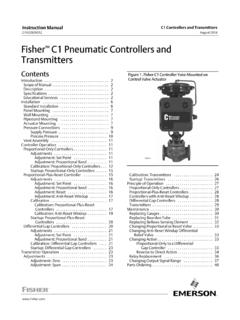
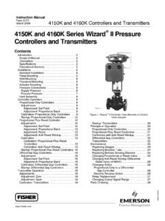
1 C1 Pneumatic Controllers andTransmittersFisher C1 Controllers and Transmitters continue thetradition of durable and dependable Fisher pressureinstrumentation while addressing air/gas consumptionconcerns. The C1 is used wherever durable anddependable pressure instrumentation is required. Theuse of this product in demanding applications, such asthose found in chemical process, gas, and oilproduction industries, demonstrates its versatility. TheC1 can reduce steady-state air/gas consumption to aslittle as 1/10th that of previous Controllers compare sensed process pressure (ordifferential pressure) with an operator-adjusted setpoint, and send a Pneumatic signal to an adjacentcontrol element that maintains the process pressure ator near the set point value. C1 Transmitters senseprocess variables and send out a Pneumatic signal,usually to an indicating or recording device thatdirectly indicates the process otherwise noted, all NACE references are toNACE MR0175 / ISO15156 & NACE Wide Range of Sensing Elements A Bourdon tube isavailable for high pressures or bellows for vacuumand low pressures.
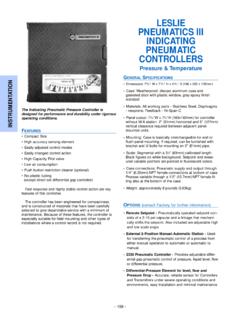
2 Either kind of sensing elementcan be installed in the case with the controller ortransmitter. Two interchangeable ranges of outputbellows and gauges also are Reduced Air/Gas Consumption The C1 pneumaticcontroller is an energy efficient choice, helping toimprove profits and uptime. Steady-stateconsumption rate is less than the 6 scfhrequirement set for the oil and gas industry by theUS Environmental Protection Agency (New SourcePerformance Standards Subpart OOOO,EPA HQ QAR 2010-0505). Fisher C1 Pneumatic CONTROLLERYOKE-MOUNTED ON CONTROL VALVE ACTUATORn Sour Service Capability Materials are available forapplications handling sour process fluids. Theseconstructions comply with the metallurgicalrequirements of NACE MR0175 / ISO15156 & NACEMR0103. Environmental restrictions may Mounting Versatility Install the case on a panel,wall or pipestand, as well as directly on the controlvalve Reduced Maintenance Costs A spring-out cleaningwire, shown in figure 4, provides for in-servicecleaning of the relay Proportional-Only, Proportional-Plus-Reset, andDifferential Gap Configurable The C1 controllercan be configured to provide various modes ofcontrol.
3 (Features continued on page 3)C1 Controllers and TransmittersD103291X012 Product :C1 August 2017C1 Controllers and TransmittersD103291X012 Product :C1 August 2017 2 SpecificationsAvailable ConfigurationsSee table 1 Input SignalPressureType: JGauge pressure, Jvacuum, Jcompoundpressure, or Jdifferential pressure of a liquid or gasLimits: See table 2 or 3 Output SignalProportional or Proportional-Plus-Reset Controllersand Transmitters : to bar (3 to 15 psig) to bar (6 to 30 psig) Pneumatic pressuresignalDifferential Gap Controllers : J0 and bar (0 and 20 psig) or J0 and bar (0 and 35 psig) Pneumatic pressure signalAction: Control action is field reversible betweenJdirect (increasing sensed pressure producesincreasing output signal) and Jreverse (increasingsensed pressure produces decreasing output signal).Supply Pressure Requirements(1)See table 4 Supply Pressure MediumAir or Natural GasSupply medium must be clean, dry, and noncorrosiveand meet the requirements of ISA Standard orISO maximum 40 micrometer particle size in the airsystem is acceptable.
4 Further filtration down to 5micrometer particle size is recommended. Lubricantcontent is not to exceed 1 ppm weight (w/w) orvolume (v/v) basis. Condensation in the air supplyshould be minimizedSteady-State Air Consumption(2)(3) to bar (3 to 15 psig): normal m3/hour(3 scfh) to bar (6 to 30 psig): normal m3/hour ( scfh)Supply and Output Connections1/4 NPT internalSupply and Output Pressure Gauge RangesSee table 5 Proportional Band AdjustmentFor Proportional-Only Controllers : Full outputpressure change adjustable from J2% to 100% of thesensing element range for to bar (3 to 15 psig)or J4% to 100% of the sensing element range for bar (6 to 30 psig)For Proportional-Plus-Reset Controllers : Full outputpressure change adjustable from J3% to 100% of thesensing element range for to bar (3 to 15psig), or J6% to 100% of the sensing element rangefor to bar (6 to 30 psig)Differential Gap AdjustmentFor Differential Gap Controllers .
5 Full output pressurechange adjustable from 15% to 100% of sensingelement rangeReset AdjustmentFor Proportional-Plus-Reset Controllers : Adjustablefrom to 74 minutes per repeat (100 to per minute)Zero Adjustment ( Transmitters Only)Continuously adjustable to position span of less than100% anywhere within the sensing element rangeSpan Adjustment ( Transmitters Only)Full output pressure change adjustable from 6 to100% of process sensing element rangePerformanceRepeatability: of sensing element rangeDead Band (Except Differential Gap Controllers (4)) of sensing element rangeTypical Frequency Response at 100% ProportionalBand:Output to Actuator: Hz and 110 degree phase shiftwith 1850 cm3 (113 inches3) volume actuator atmid-strokeOutput to Positioner Bellows: 9 Hz and 130 degreephase shift with to bar (3 to 15 psig) output to33 cm3 ( 2 inches3 ) bellows-continued-C1 Controllers and TransmittersD103291X012 Product :C1 August 2017 3 Specifications (continued)Ambient Operating Temperature Limits(1)JStandard Construction: -40 to 71_C (-40 to 160_F)JHigh Temperature Construction: -18 to 104_C (0 to 220_F)Anti-reset windup (differential pressure relief) andprocess pressure gauge options are only available inthe standard constructionTypical Ambient Temperature Operating InfluenceProportional Control only: of output span foreach 28_C (50_F) change in temperature between-40 and 71_C (-40 and 160_F) for a controller set at100% proportional bandReset Control only: of output span for each28_C (50_F) change in temperature between -40 and71_C (-40 and 160_F) for a controller set at 100%proportional bandTransmitters only.
6 Of output span for each28_C (50_F) change in temperature between -40 and71_C (-40 and 160_F) for a transmitter set at 100%spanHousingDesigned to NEMA 3 (Weatherproof) and IEC 529IP54 SpecificationsHazardous Area ClassificationComplies with the requirements of ATEX Group IICategory 2 Gas and DustMeets Customs Union technical regulation TP TC012/2011 for Groups II/III Category 2 equipmentII Gb c T*XIII Db c T*XConstruction MaterialsSee tables 2, 3, and 6 Approximate kg (18 pounds)NOTE: Specialized instrument terms are defined in ANSI/ISA Standard - Process Instrument The pressure and temperature limits in this document, and any applicable standard or code limitation should not be Normal m3/hr: normal cubic meters per hour (m3/hr, 0_C and bar, absolute). Scfh: standard cubic feet per hour (ft3/hr, 60_F and psig).3. To convert from air flow rate to natural gas flow rate multiply by An adjustable differential gap (differential gap Controllers ) is equivalent to an adjustable 1.
7 Available ConfigurationsDESCRIPTION(1)AVAILABLE CONFIGURATIONSP ressureBourdon Tube Sensing Element (Gauge Pressure Only)Bellows Sensing ElementGauge PressureDifferential PressureProportional controllerC1PC1BC1 DProportional-plus-resetcontrollerWithou t anti-reset windupWith anti-reset windup- - -Differential-gap controller - - -TransmitterC1D1. See figure 4 and 5 for construction (continued)n Field Reversible Switch action from direct toreverse or vice versa without additional parts. Asillustrated in figure 3, transfer the reversing block tothe opposite side of the flapper, invert theproportional band assembly and change thefeedback bellows tubing Easy, More Accurate Adjustments Make pressureset point, proportional band, and reset changeswith simple dial-knob controls that help to assurepositive Sensitive Response Area ratio of large relaydiaphragm to small relay diaphragm permits smallnozzle pressure changes to induce much greateroutput pressure Controllers and TransmittersD103291X012 Product :C1 August 2017 4 Table 2.
8 Bourdon Tube Pressure Ranges and MaterialsPRESSURE RANGES(1)MAXIMUM ALLOWABLE STATIC PRESSURE LIMITS(2)MATERIAL(4)StandardWith Optional Travel Stop(3)BarPsigBarPsigBarPsig0 to to to to 300 to 600 to Stainless Steel0 to 140 to 200 to 400 to 700 to 2000 to 3000 to 6000 to 1000142040702003006001000192950832804207 2012000 to 1000 to 2000 to 3500 to 15000 to 30000 to 5000100200350150030005000115230380165033 0055000 to 5500 to 7000 to 80000 to 10,000550700800010,000550700800010,0001. Range marked on Bourdon tube may be in kPa (1 bar = 100 kPa).2. Bourdon tube may be pressured to limit shown without permanent zero With travel stop set at 110% of the Bourdon tubes are also available in NACE compliant material. Contact your Emerson sales office or Local Business Partner for additional 3. Bellows Pressure Ranges and MaterialsPRESSURE RANGESMAXIMUM ALLOWABLESTATIC PRESSURE LIMITS(1)Brass ConstructionStainless SteelConstructionBarPsigBarPsigGaugepres sureVacuum0 to 150 mbar (0 to 60 inch wc)0 to 340 mbar (0 to 10 inch Hg)0 to bar (0 to 30 inch Hg) - -- - - -- - -100 Compoundpressure75 mbar vac.
9 To 75 mbar (30 inch wc vac. to 30 inch wc) mbar vac. to 500 mbar (15 inch Hg vac. to psig) bar vac. to bar (30 inch Hg vac. to 15 psig) - -- - -Positivepressure0 to 150 mbar (0 to 60 inch wc)0 to 250 mbar(2) (0 to 100 inch wc)0 to 350 mbar(3) (0 to 140 inch wc)0 to bar (0 to 5 psig)0 to bar (0 to psig) - -- - -- - -- - -- - -- - -- - -- - -- - -- - -0 to bar (0 to 10 psig)0 to bar (0 to 15 psig)0 to bar (0 to 20 psig)0 to bar (0 to 30 psig) - - - -100- - -100 Differential pressure(4)0 to 200 mbar (0 to 80 inch wc)0 to bar (0 to 10 psi)0 to bar (0 to 20 psi)0 to bar (0 to 30 psi) - -204040- - -- - -- - -- - - -- - -- - -1001. Bellows may be pressured to limit shown without permanent zero C1B transmitter Except C1B The overrange limit for these sensing elements is a differential pressure equal to the maximum allowable static pressure 4. Supply Pressure DataOutput SignalNormal Operating SupplyPressure(1)Maximum Allowable Supply Pressure To PreventInternal Part Damage(2) to or 0 and (differential gap) to or 0 and (differential gap) to 15 or 0 and 20 (differential gap)20406 to 30 or 0 and 35 (differential gap)35401.
10 If this pressure is exceeded, control may be If this pressure is exceeded, damage to the controller may Controllers and TransmittersD103291X012 Product :C1 August 2017 5 Table 5. Supply and Output Pressure Gauge RangesGauge to Bar (3 to 15 Psig) or0 and Bar (0 and 20 Psig) to Bar (6 to 30 Psig) or0 and Bar (0 and 35 Psig) OutputSingle0 to 30 psig0 to 2 kg/cm20 to 200 kPa0 to 60 psig0 to 4 kg/cm20 to 400 kPaDual0 to 30 psig/0 to 200 kPa0 to 60 psig/0 to 400 kPaTriple0 to 30 psig/0 to 2 kg/cm2/0 to 2 bar0 to 60 psig/0 to 4 kg/cm2/0 to 4 barTable 6. Construction MaterialsPartMaterialIn contact withprocessBourdon tubeStainless steel or NACE compliant N04400 nickel alloy(1)Sensing bellowsBrass or stainless steelPressure blockStainless steel or NACE compliant stainless steel(1)Control tubing (from pressure block to sensing elementand to optional process pressure gauge)Stainless steel or NACE compliant stainless steel(1)In contact withoperatingmediumAll other interior tubingStainless steelExterior tubingCopper (with or without PVC plastic lining), stainless steel, orsynthetic rubberExterior fittingsBrass or stainless steelNozzle and reversing blockZinc/stainless steelRelay springs and spring plateSteelRelay diaphragmsNitrile/nylon (standard) or polyacrylate/nylon (high-temperature)