Transcription of Fisher POSI-SEAL A31A High Performance Butterfly Valve NPS ...
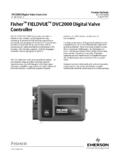
1 POSI-SEAL a31a high PerformanceButterfly Valve NPS 3 through of the Actuator Travel Stops or for Wafer Style Single Flange the Valve from the the Seal Seal Seal and Phoenix III Fire Tested Seal Seal Blowout Protection, Packing, Valve Shaft(s), Disk, and Bearing a One Piece a Two Piece the Gasket 1. Typical Fisher a31a ValveW5812 1W5811 1 Parts of ManualThis instruction manual provides installation, maintenance, and parts ordering information for the Fisher POSI SEALA31A high Performance Butterfly valves . Figure 1 shows typical a31a valves . For information regarding actuators andaccessories, refer to separate instruction not install, operate, or maintain a31a valves without being fully trained and qualified in Valve , actuator, andaccessory installation, operation, and maintenance.
2 To avoid personal injury or property damage, it is important tocarefully read, understand, and follow all the contents of this manual, including all safety cautions and warnings. If youhave any questions about these instructions, contact your Emerson sales office or Local Business Partner ManualD500240X012A31A ValveFebruary 2018 Instruction ManualD500240X012A31A ValveFebruary 20182 Table 1. SpecificationsAvailable Valve ConfigurationsJFlangeless, wafer style or Jsingle flange (lugged)control Valve with a one piece Valve body and atwo component seal/backup O ring, and a keyeddrive shaftValve SizesNPS J3, J4, J6, J8, J10, J12 End Connection StyleJFlangeless, wafer style or Jsingle flange valvebody designed to fit between raised face matingflanges per ASME CL150 or CL300 Maximum Inlet Pressure/Temperature(4)Consistent with ASME JCL150 and JCL300pressure/temperature ratings per ASME Also,see figure 2 for additional Seal ConfigurationsJStandard soft seal ring (PTFE) with fluorocarbon orEPR backup ring, JNOVEX seal ring, CL150,(S31600, 316 SST)(1)
3 JNOVEX seal ring, CL300,standard pressure rating (S31600, 316 SST)(1)JNOVEX seal ring, CL300, high pressure rating(S21800), JPhoenix III fire tested seal ring (S31600,316 SST) with resilient insert (PTFE) and backup ring(fluorocarbon), or Jcryogenic seal ring (CTFE) withoptional backup ring (aluminum) Valve ClassificationFace to face dimensions are in compliance with MSSSP68 and API 609 standards; Valve bodies aredesigned for installation between ASME CL150or 300 raised face flangesShutoff Classification. Per ANSI/FCI 70 2 Standard Soft Seal: Bidirectional bubble tight shutoffNOVEX Seal: Unidirectional shutoff Class V (reverseflow direction only)Phoenix III Seal: Bidirectional bubble tight shutoffPhoenix III Seal for Fire Tested Applications: Consultyour Emerson sales office or Local Business Partner forfire tested performanceCryogenic seal applications: Consult your Emersonsales office or Local Business PartnerInstalled Valve OrientationSee figure 3 for orientation guidelines for optimumseal performanceValve In Line PositionShaft horizontal.
4 See figure 5 Available ActuatorsJHandlever, Jhandwheel,Jspring and diaphragm, or Jpneumatic pistonDisk RotationClockwise to close1. For specific information about materials of construction, contact your nearest Emerson sales office or Local Business The pressure/temperature limits in this manual, and any applicable code or standard limitation, should not be a31a high Performance Butterfly Valve features a keyed drive shaft. The keyed shaft combines with a variety ofhandlevers, handwheels, pneumatic piston or spring and diaphragm actuators to make the a31a a reliable, high Performance , Butterfly Valve for a variety of applications in the various process a31a is available in either a flangeless (wafer) or a single flange (lugged) Valve design, with a variety of seal, valvebody, and internal components.
5 The a31a Valve features a dynamic sealing design that is used in a variety ofdemanding applications. With the appropriate seal configuration and materials of construction, the pressure assistedseal provides shutoff against the full ASME class pressure range for the specific Valve ManualD500240X012A31A ValveFebruary 20183 Educational ServicesFor information on available courses for the Fisher POSI-SEAL A31 NPS 3 through 12 Butterfly Valve , as well as a varietyof other products, contact:Emerson Automation SolutionsEducational Services - RegistrationPhone: 1-641-754-3771 or 1-800-338-8158E-mail: WARNINGA lways wear protective gloves, clothing, and eyewear when performing any installation operations to avoid avoid personal injury or property damage resulting from the sudden release of pressure, do not install the valveassembly where service conditions could exceed the limits given in this manual or on appropriate nameplates.
6 Usepressure relieving devices as required by government or accepted industry codes and good engineering with your process or safety engineer for any additional measures that must be taken to protect against installing into an existing application, also refer to the WARNING at the beginning of the Maintenance section in thisinstruction Valve configuration and construction materials are selected to meet particular pressure, temperature, pressure drop,and controlled fluid conditions. Because pressure drop and temperature range capabilities limit some combinations ofmaterials, do not apply any other conditions to the Valve without first contacting your Emerson sales office or LocalBusiness maximum allowable inlet pressures for a31a valves are consistent with the applicable pressure/ temperatureratings except where limited by material capabilities shown in figure 2 and table the Actuator Travel Stops WARNINGThe edges of a rotating Valve disk have a shearing effect that may result in personal injury.
7 To avoid personal injury, keepclear of the disk edges when rotating the ManualD500240X012A31A ValveFebruary 20184 CAUTIONWhen using an actuator, the actuator travel stops or the actuator travel (for actuators without adjustable stops) must beadjusted so that the disk stop in the Valve body does not absorb the output of the actuator. Failure to limit actuator travelas described in the next step can result in damage to the Valve shafts or other Valve Locate the actuator travel stop that establishes the closed position of the Valve disk. When adjusting the travel stopor travel, make sure that the disk is from to inch ( to mm) away from the internal stop in thevalve body. This adjustment is necessary to be certain that the actuator output torque is fully absorbed by theactuator travel stop or by the actuator.
8 The internal travel stop in the Valve body should not absorb any of theactuator Before installing the Valve /actuator assembly in the process line, cycle the Valve several times to be sure the valvedisk returns to the proper 2. Material Temperature RatingsCOMPONENT, ASME CLASS, MATERIAL OF CONSTRUCTIONTEMPERATURE RANGE_F_CSeal RingSee Figure 2 Backup Ring Soft Seal Fluorocarbon EPR Nitrile PTFE Chloroprene Phoenix III Seal Fluorocarbon EPR Nitrile Chloroprene Cryogenic Seal Aluminum (Optional) 20 to 400 65 to 360 20 to 200 100 to 400 45 to 300 40 to 500 80 to 400 40 to 300 65 to 300 425 to 400 29 to 204 54 to 182 29 to 93 73 to 204 43 to 149 40 to 260 62 to 204 40 to 149 59 to 149 254 to 204 Shaft Packing(1) PTFE Graphite In Oxidizing Media In Inert or Reducing Media 425 to 450 425 to 1000 425 to 1500 254 to 232 254 to 538 254 to 816 Shaft(2)
9 17 4PH H1025 17 4PH H1150M N05500 N07718 S20910 100 to 800 320 to 800 425 to 900 425 to 1300 320 to 1100 73 to 427 195 to 427 254 to 482 254 to 704 196 to 593 Bearings PEEK(3) (standard) 316 SST PTFE Composition Bronze 100 to 500 425 to 1500 425 to 325 425 to 500 73 to 260 254 to 816 254 to 163 196 to 260 Disk Hardfacing Electroless Nickel Plating or hard chrome coating CoCr A(4) (Alloy 6) 425 to 1000 325 to 1500 254 to 538 198 to 8161. These low temperature limits apply to the flowing media. Valve extensions provided for cryogenic service maintain higher temperatures at the packing Shaft material may affect the Valve pressure rating. Consult your Emerson sales office or Local Business PEEK stands for PolyEtherEtherKetone4.
10 CoCr A hardfacing degrades shutoff Performance of the seal. Consult your Emerson sales office or Local Business ManualD500240X012A31A ValveFebruary 20185 Valve OrientationNoteThe NPS 10 through 12 CL150 valves and NPS 8 through 12 CL300 valves have a two piece shaft. The shaft with the keyed end iscalled the drive shaft. The shaft opposite the drive shaft is called the follower NPS 3 through 8 CL150 valves and NPS 3 through 6 CL300 valves have a one piece shaft. This one piece shaft is keyed and iscalled the drive possible, install the Valve with the shaft in the horizontal position as shown in figure installation can enhance Valve Performance because process fluid flow will sweep entrained solids from Valve surfaces,preventing particle buildup on the seal.