Transcription of Fisher Vee‐Ball V150, V200, and V300 Rotary Control Valves ...
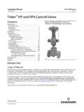
1 Instruction Manual Vee-Ball Valves D101554X012 June 2017. Fisher Vee Ball V150, V200 and v300 Rotary Control Valves NPS 1 through 12. Contents Figure 1. Fisher Vee Ball with 2052 Actuator Introduction .. 1 and FIELDVUE dvc6200 digital Valve controller Scope of Manual .. 1. Description .. 2. Specifications .. 2. Educational Services .. 2. Installation .. 3. Maintenance .. 9. Packing Maintenance .. 9. Replacing the Ball Seal .. 11. Disassembly .. 11. Assembly .. 14. HD Ball Seal Lubrication .. 20. Bearing and Ball Maintenance .. 20. DN 80 - 300 (NPS 3 - 12) Valves .. 20. Welded Taper Key Replacement .. 24. DN 25 - 50 (NPS 1 - 2) Valves .. 25. Actuator Mounting .. 32. NPS 3 through 12 without Attenuator .. 32. Determining Mounting Position.
2 33. Determining Closed Position .. 33. Parts Ordering .. 39. Parts Kits .. 40. Parts List .. 41 X0187. Appendix A instructions for Non Series B .. 42. Introduction Scope of Manual This instruction manual provides installation, operation, maintenance, and parts information for the Fisher Vee Ball V150 (NPS 1 through 12), V200 (NPS 1 through 10), and v300 (NPS 1 through 12) Rotary Control Valves (see figure 1). NPS 3 through 12 Valves without an attenuator currently in production are referred to as Series B (for more information on this distinction see Appendix A). For larger Valves (NPS 14, 16, and 20), refer to a separate instruction manual. For information on ENVIRO SEAL . packing, see the ENVIRO SEAL Packing System for Rotary Valves instruction manual (D101643X012).
3 Refer to separate manuals for information concerning the actuator, positioner and accessories. Do not install, operate, or maintain Vee-Ball Valves without being fully trained and qualified in valve, actuator, and accessory installation, operation, and maintenance. To avoid personal injury or property damage, it is important to carefully read, understand, and follow all the contents of this manual, including all safety cautions and warnings. If you have any questions about these instructions , contact your Emerson sales office or Local Business Partner before proceeding. Vee-Ball Valves Instruction Manual June 2017 D101554X012. Table 1. Specifications Valve Sizes Actuator Mounting See table 2 J Right hand, standard or J left hand, optional, as viewed from upstream end of valve (see figure 23 and Valve End Connection Styles the Actuator Mounting section).
4 V150: Flanged Valves that mate with CL150. raised-face flanges and EN 1092-1 Type B raised-face Maximum Ball Rotation and Type F Recess Standard: Ball rotates counterclockwise to close V200: Flangeless (all sizes) and flanged Valves that when viewed from actuator side of valve mate with CL600 raised-face flanges (NPS 2-8). Optional: Ball rotates clockwise to close v300 : Flanged Valves that mate with CL300. raised-face flanges and EN 1092-1 Type B raised-face Ball rotation is 90 degrees and Type F Recess Maximum Inlet Pressure(1) Valve/Actuator Action Consistent with applicable ASME or With diaphragm or piston Rotary actuator, EN 12516-1 ratings field reversible between:J push down to close (extending actuator rod closes valve) and Standard Flow Direction J push down to open (extending actuator rod Forward (into the convex face of the Vee ball) opens valve.)
5 See actuator manual for details 1. The pressure/temperature limits in this manual, and any applicable code or standard limitation, should not be exceeded. Description The V150, V200, and v300 Vee Ball Valves (figure 1) with a V notch ball are used in throttling or on off service. The V200 is a flangeless construction. The V150 and v300 Valves are raised face flanged constructions. The splined valve shaft of all these Valves connect to a variety of Rotary shaft actuators. Specifications Specifications for these Valves are shown in table 1 and in the Fisher Vee-Ball V150, V200, and v300 Rotary Control Valves Bulletin :Vee Ball (D101363X012). Educational Services For information on available courses for Fisher Vee-Ball Valves , as well as a variety of other products, contact: Emerson Automation Solutions Educational Services - Registration Phone: 1-641-754-3771 or 1-800-338-8158.
6 E-mail: 2. Instruction Manual Vee-Ball Valves D101554X012 June 2017. Table 2. Valve Body Materials, End Connections, and Ratings SIZE RATINGS. VALVE DESIGN VALVE BODY MATERIAL. NPS / DN ASME / PN. WCC NPS 1, 1-1/2, 2, 3, 4, 6, 8, 10, 12, 14, 16, 20, 24x20(5) CL150. DN 80, 100, 150 PN 10-16. WCC / (1). DN 200, 250, 300 PN 10 or PN 16. NPS 1, 1-1/2, 2, 3, 4, 6, 8, 10, 12 CL150. LCC DN 80, 100, 150 PN 10-16. DN 200, 250, 300 PN 10 or PN 16. CF3M(2) NPS 1, 1-1/2, 2, 3, 4, 6, 8, 10, 12 CL150. V150 DN 80, 100, 150 PN 10-16. CF3 (1). DN 200, 250, 300 PN 10 or PN 16. CG8M NPS 1, 1-1/2, 2, 3, 4, 6, 8, 10, 12, 14, 16, 20, 24x20(5). CW2M NPS 1, 1-1/2, 2, 3, 4, 6, 8, 10, 12. M35-2 NPS 1, 1-1/2, 2, 3, 4, 6, 8. CL150. CD3MN(3) NPS 1, 1-1/2, 2, 3, 4, 6, 8, 10, 12.
7 CD3 MWCuN(3) NPS 1, 1-1/2, 2, 3, 4, 6, 8, 10, 12. CK3 MCuN NPS 1, 1-1/2, 2, 3, 4, 6, 8, 10, 12. NPS 1, 1-1/2, 2 CL150/300/600 flangeless CL150 and CL300/600. NPS 3, 4. flangeless WCC, LCC, CG8M, or CF3M(2). CL150/300 and CL600. NPS 6, 8. V200(4) flangeless NPS 10 CL150 flangeless WCC, LCC, or CG8M NPS 2, 3, 4, 6, or 8 CL600. CW2M, M35-2, or CK3 MCuN NPS 1, 1-1/2, 2, 3, 4, 6, 8 CL150/300/600 flangeless CK3 MCuN NPS 10 CL150 flangeless WCC NPS 1, 1-1/2, 2, 3, 4, 6, 8, 10, 12, 14, 16, 20 CL300. DN 25, 40, 50 PN 10-40. WCC / (1) DN 80, 100, 150 PN 25-40. DN 200, 250, 300 PN 25 or PN 40. NPS 1, 1-1/2, 2, 3, 4, 6, 8, 10, 12 CL300. DN 25, 40, 50 PN 10-40. LCC. DN 80, 100, 150 PN 25-40. DN 200, 250, 300 PN 25 or PN 40. CF3M(2) NPS 1, 1-1/2, 2, 3, 4, 6, 8, 10, 12 CL300.
8 v300 . DN 25, 40, 50 PN 10-40. CF3 (1) DN 80, 100, 150 PN 25-40. DN 200, 250, 300 PN 25 or PN 40. CG8M NPS 1, 1-1/2, 2, 3, 4, 6, 8, 10, 12, 14, 16, 20. CW2M NPS 1, 1-1/2, 2, 3, 4, 6, 8. M35-2 NPS 1, 1-1/2, 2, 3, 4, 6, 8. CL300. CD3MN(3) NPS 1, 1-1/2, 2, 3, 4, 6, 8, 10, 12. CD3 MWCuN(3) NPS 1, 1-1/2, 2, 3, 4, 6, 8, 10, 12. CK3 MCuN NPS 1, 1-1/2, 2, 3, 4, 6, 8, 10, 12. 1. WCC and EN Stl are dual certified. CF3M and EN SST are dual certified. 2. CF3M is a standard offering in Europe and Asia Pacific. 3. NORSOK compliant materials available upon request. 4. Flangeless V200 assemblies mate with raised-face flanges. 5. Valve body mates with NPS 24 ASME CL150 flanges. Internal based on NPS 20 valve design. Installation Separate installation steps are provided in this section for V150 and v300 flanged Valves , and for V200 flangeless Valves .
9 Key numbers in installation procedures are shown in figures 24, 25 and 26 unless otherwise indicated. Some types of ceramic trim, including VTC, can create a spark under certain conditions. If an edge of a ceramic part is struck against a second ceramic part with enough force, it can produce a spark. 3. Vee-Ball Valves Instruction Manual June 2017 D101554X012. WARNING. Avoid personal injury and property damage from ignition of process fluid caused by sparks from ceramic trim. Do not use ceramic trim where the process fluid is unstable or if it is an explosive mixture (such as ether and air). WARNING. Always wear protective gloves, clothing, and eyewear when performing any installation operations to avoid personal injury. Personal injury or equipment damage caused by sudden release of pressure may result if the valve assembly is installed where service conditions could exceed either the valve body rating or the mating pipe flange joint rating.
10 To avoid such injury or damage, provide a relief valve for overpressure protection as required by government or accepted industry codes and good engineering practices. Check with your process or safety engineer for any additional measures that must be taken to protect against process media. If installing into an existing application, also refer to the WARNING at the beginning of the Maintenance section in this instruction manual. Figure 2. Flange Stud Length for Seal Protector End DIMENSION SHOWN IN TABLE 3. FIRST FULL THREAD TO. FIRST FULL THREAD. 1A4520. Table 3. Flange Stud Lengths Required for Seal Protector Ring End of Fisher V150 and v300 Valves V150 V200(1) v300 . VALVE. ANSI/ISA ASME Short ANSI/ISA ANSI/ISA SIZE. Face to Face Face to Face Face to Face Face to Face DN NPS mm Inches mm Inches mm Inches mm Inches 25 1 70 95 --- --- 89 40 1-1/2 83 127 --- --- 102 50 2 95 146 121 95 80 3 95 133 140 121 100 4 108 146 165 127 150 6 114 152 197 140 200 8 121 171 216 152 250 10 133 165 --- --- 171 300 12 140 159 --- --- 184 1.