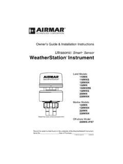
Transcription of Fits Models: B44V, B66V, B66VL. B744V, B744VL
1 17-207-02 rev. 0407/17/14 Thru-Hull, Spares KitPaddlewheel & Valve Kit 33-218 Fits Models: b44v , b66v , b66vl . b744v , B744 VLServicingCAUTION: Be careful to avoid cross threading the cap O-rings must be intact and well lubricated to make a watertight seal. Lubricate the replacement O-rings with silicone lubricant or petroleum jelly (Vaseline ). Replace the two O-rings near the bottom of the blanking plug. Do not place them near the pull ring (see Figure 1).2. Remove the safety wire and unscrew the cap nut. With the blanking plug ready in one hand, remove the paddlewheel insert and valve assembly as one unit by grasping the pull ring and pulling upward. Rapidly insert the blanking plug to minimize the flow of water into the boat. TEMPORARILY hold the plug in place with the safety wire (see Figures 2 and 3). This is NOT a watertight or secure seal! Do not leave the boat in the water Separate the paddlewheel insert from the valve assembly by removing the safety ring and the retaining pin.
2 Grasp the insert by the pull ring and pull slowly 3. Installation with strap ( b744v shown)O-ringsFigure 1. Blanking plug ( b744v shown)pull ringpull ringretaining pinhullsafety wirecap nuthull nutbackingstemcableblocksafety strapsafety ringCopyright 2005 Airmar Technology 2005 Airmar Technology the precautions below for optimal product performance and to reduce the risk of property damage, personal injury, and/or : The valve assembly must be in the housing to make a watertight seal. When the valve assembly is removed, the blanking plug cannot prevent water from seeping into the boat. Never leave the boat in the water UNATTENDED without the valve assembly in the housing and the paddlewheel insert or blanking plug : Always wear safety goggles and a dust mask when : O-rings must be intact and well lubricated to make a watertight : Always attach the safety wire to prevent the insert from backing out in the unlikely event that the cap nut and/or insert nut fails or is screwed on : Never use solvents.
3 Cleaner, fuel, sealant, paint, and other products may contain solvents that can damage plastic parts, especially the transducer s : Please read the instructions completely before proceeding with the installation. These instructions supersede any other instructions in your instrument manual if they 2. Installation with chain ( b744v shown)pull ringretaininghullsafetysafetysafetycap nuthull nutbackingstemcableblockringchainpinwire Copyright 2005 Airmar Technology INSTRUCTIONS4. Check the new valve assembly to see that the flap valve moves freely and seats against the sleeve (see Figure 4). Discard the old valve assembly. 5. To service the paddlewheel insert, use the new paddlewheel shaft to push the old shaft out about 6 mm (1/4"). With pliers, remove the old shaft (see Figure 5).6. Remove any aquatic growth from the insert using a stiff brush or putty knife.
4 Clean the surface with mild household detergent and a Scotch-Brite scour pad. If fouling is severe, lightly wet sand it with fine grade wet/dry Place the new paddlewheel in the cavity with the flat side of the blade facing the same direction as the arrow on the top of the Tap the new shaft into place until the ends are flush with the the two O-rings in the groves near the paddlewheel. Do not place them near the pull ring. Lubricate the O-rings with silicone lubricant or petroleum jelly (Vaseline ). the paddlewheel insert into the valve assembly. Seat it into place with a twisting motion until the keys fit into the notches. Secure the paddlewheel insert with the retaining pin and safety ring(s) (see Figures 2 and 3). the valve assembly by first removing the safety wire from the blanking plug. With the valve assembly/insert ready in one hand, remove the blanking plug.
5 Slide the valve assembly into the multisensor housing with the arrow on the top pointing forward toward the bow. Be sure the cable fits into the cable channel and the key in the housing fits into the notch in the sleeve (see Figure 4). (A pushing twisting motion will locate the key.) Screw the cap nut in place. Be careful to avoid cross threading the cap nut. Hand-tighten only. Do not over attach the safety wire to prevent the insert from backing out in the unlikely event that the cap nut and/or insert nut fails or is screwed on incorrectly. Reattach the safety wire (see Figures 2 and 3).2 Figure 5. Servicing ( b744v shown)BOW flat side of paddlewheel O-ringspaddlewheelpull ringshaftcap nutpaddlewheeltop view ofhousing andblade facespaddlewheelinsertinsertvalve assemblyhousingnotcheskey (2)valveassemblyinsert detailcableblankingplugdirection ofarrow on topof insert (toward bow)Antifouling PaintSurfaces exposed to salt water must be coated with antifouling paint.
6 Use water-based antifouling paint only. Never use ketone-based paint, since ketones can attack many types of plastic possibly causing damage. Paint the following surfaces. Exposed areas of the housing including the transducer s face Bore of the housing up 30 mm (1-1/4") Outside wall below lower O-ring of paddlewheel insert Paddlewheel cavity Paddlewheel Blanking plug below lower O-ring including exposed endFigure 4. Valve assembly ( b744v shown)sleeve flap valvespring pinspringnotchcable channelCopyright 2005 Airmar Technology 2005 Airmar Technology 2005 - 2014 Airmar Technology Corp. All rights reserved. 35 Meadowbrook Drive, Milford, New Hampshire 03055-4613, USA