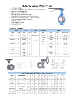
Transcription of Fixed Displacement Radial Piston Hydraulic Motor Data ...
1 Industrial ProductsMotorsIssue 03/00 Size 50 to 11,600cc/rev,up to 250 bar,36,000Nm, 240kW Fixed Displacement Radial Piston Hydraulic MotorStaffa, Series B Data Sheet M-1001 GBFeatures Rugged, reliable, proven design. Unique Hydrostatic balancing providesminimum wear and extended life. High volumetric and mechanical efficiency. Capacities range from 50 to 11600 cc per rev. Large variety of Shaft and Porting options. Output torque up to 36000 Nm. Wide range of mounting interfaces available. Highly accurate electronic positional andvelocity control systems also available.
2 DescriptionThe Kawasaki Staffa range of high torque low speed Fixed Displacement Radial Piston Hydraulic motorsconsists of 13 frame sizes ranging from the HMB010 to HMB700. Capacity ranges from 50 to 11,600 rugged, well proven design incorporates high efficiency, combined with good breakout torque andsmooth running features and options are available including, on request, mountings to match competitors interfaces. The Kawasaki Staffa range also includes dual and continuously variable Displacement motors. To obtaindetails of this product range please refer to data sheet M-1002 ModelStaffa SheetM-1001 ProductsIssue 03/00 Ordering Code Staffa Motor Series B ModelStaffa SheetM-1001 TypeSee shaft type option list on Page 3 Fluid TypeBlank:Mineral :Phosphate ester(HFD fluid).
3 F11:Water-basedfluids (HFA, HFB& HFC) * :ConsultKkiSpecial FeaturesPL**: Non-cataloguedfeatures, (**)=number assignedas :Stainless steel Port ConnectionsSee Port Connection details on Page 4 Model TypeBlank:Standard (HMB)HD:Heavy duty (HMHDB)F11HM*BS3FM3PL**TxDesign Series NumberTacho/Encoder DriveBlank:NoneT:Staffa original tacho :Customer specificencoder Size(See options page 7)Industrial ProductsMotorsIssue 03/00 Shaft OptionsMOTOR TYPESHAFT DESCRIPTIONHMB010P* = Parallel keyed shaft 40mmHMB010 S* = Involute spline 13 teeth BS3550 HMB030/045 (H)S* = Involute spline 17 teeth to BS3550 HMB030/045(H)P=Parallel keyed shaft 55mmHMB030/045 (H)Z* = Involute spline to DIN5480 (W55x3x17x7h)HMB045 Q* = Internal involute spline 21 teeth to BS3550 HMB060/080/100 (H)P* = Parallel keyed shaft 60mmHMB060/080/100(H)S* = Involute spline14 teeth to BS3550 HMB060/080/100 (H)
4 Z* = Involute spline to DIN5480 (W70x3x22x7h)HMB060/080/100(H)Q* = Internal involute spline 24 teeth to BS3550 HMB060/080/100/125/150/200/HMB270/325 T*= Long tapered keyed shaftHMB060/080/100/270/325 X* = Short tapered keyed shaftHMB125/150/200/270/325(H)P1* = Parallel keyed shaft 85mmHMHDB125/150/200/270 & 325 (H)P2* = Parallel keyed shaft 100mmHMB125/150/200/270/325 (H)S3* = Involute spline 20 teeth to BS3550 HMB125/150/200(H)S4* = Involute spline 16 teeth at 200 HMHDB125/150/200, 270/325 (H)S5* = Involute spline 23 teeth to BS3550 HMB125/150/200 (H)Z3* = Involute spline to DIN5480 (W85x3x27x7h)HMHDB125/150/200(H)Z5* = Involute spline to DIN5480 (W100x4x24x7h)HMHDB125/150/200/270/325 (H)Q* = Internal involute spline 34 teeth to BS3550 HMHDB125/150/200/270/325 (H)X* = Short taper, keyed shaftHMB270/325 + HMHDB270/325(H)Z* = Involute spline to DIN5480 (W100x4x24x7h)HMHDB400P* = Parallel shaft with two keys 100mmHMHDB400 S* = Involute spline 23 teeth to BS3550 HMHDB400 Z* = Involute spline to DIN5480 (W100x4x24x7h)
5 HMHDB400 Q*= Internal involute spline 31 teeth to BS3550 HMHDB400 X* = Tapered keyed shaftHMB700 Z* = Involute spline to DIN5480 (W120x4x28x7h)HMB700P=Parallel keyed shaft at 1200 120 Notes:* - For installations where shaft is vertically upwards specify V after shaft type letter to ensure thatadditional high level drain port is provided.(H) - Use H prefix code as noted to specify hollow shaft with through hole Hollow shafts areavailable only with type S04 main port all shaft dimensions see the Motor installation drawings ModelStaffa SheetM-1001 ProductsIssue 03/00 Main Port ConnectionsProduct TypeHMB010 Blank=Two, four bolt flange ports of 20mm HMB030 Mono blocBlank = Rear entry ports G 3 /4" (BSPF)F = Side port SAE 1" -4 Bolt (UNC) flangeFM = Side port SAE 1" -4 Bolt (Metric) flangeHMB045 Mono blocBlank = Rear entry ports G 1" (BSPF)D = Dual entry ports G 1" (BSPF)
6 HMB030/045 Two part build (TPB)See detail belowHMB060/080/100F2 =SAE 1", 4 Bolt (UNC) flangesFM2 = SAE 1", 4 Bolt (Metric) flangesS03= 6-Bolt (UNF) flange. (Staffa original valve housing)F3 = SAE 11/4 4 Bolt (UNC) flangesFM3 = SAE 11/4" 4 Bolt (Metric) flangesS04 (1) = 6 Bolt (UNF) flanges. (Staffa original valve housing)HMB125/150/200 + Heavy Duty Variants Details as above, plus the following:F4 = SAE 11/4" 4 Bolt (UNC) flangesFM4 = SAE 11/2" 4 Bolt (Metric) flangesHMB270/325 + Heavy Duty VariantsF4 = SAE 11/2" 4 Bolt (UNC) flangesFM4 = SAE 11/2" 4 Bolt (Metric) flangesS04 (1) = 6 Bolt (UNF) flanges.
7 (Staffa original valve housing)HMHDB400 Blank = Combined 6-Bolt flange and 4 Bolt SAE connectionPorts B and C 6-Bolt UNF flangePorts A and C SAE, 2" 4-Bolt UNF flangesS045 = 2 x 6 Bolts (UNF) flanges (2 inlet and 2 outlet ports available)HMB700FM = Standard code 62 SAE 2" 4 Bolt (Metric) flangesNote:(1)Obligatory for hollow shafts type: HP, HS, HZ or HQ ModelStaffa SheetM-1001 ProductsMotorsIssue 03 Symbols SheetM-1001 (Mono Block)HMB045-**D-30(Mono Block)HMB045-**-30-F(M)3-; F(M)4-HMB030*/045*(TPB)HMB060/080 HMB100/125 HMB150/200*F(M)3 ONLY-F(M)2-;-S03-;-S04-HMB030-045(TPB)HM B060/080 HMB100/125 HMB150/200-F(M)4-HMB270 HMB325-S04-HMB270 HMB325 HMHDB400-**-S045-030 Dual portsHMB 700 HMHDB400-**-030 RemovableplugMotorsIndustrial ProductsIssue 03/00 Performance DataIntermittent max pressureB010 up to 241 barB700 up to 250 barAll other models to 293 pressures are allowable on the following basis:(a) Up to 50 r/min: 15% duty for periods up to 5 minutes maximum.
8 (b) Over 50 r/min: 2% duty for periods up to 30 seconds ratingFor continuous duty the Motor must be operating within each of the maximum values for speed, pressureand ratingOperation within the intermittent power rating (up to the maximum continuous speed) is permitted on a 15%duty basis, for periods up to 5 minutes for fire resistant fluidsPressure, barFluid TypeContinuousIntermittentMax Speed r/minModel typeHFA 5/95% oil inemulsion10313850% of limits forMineral OilAll modelsHFB 60/40 water inoil emulsion138172As for Mineral OilAll modelsHFC water glycol10313850% of limits orMineral OilAll modelsHFD phosphateester207241As for Mineral OilB010207293B030250293B045 to B400 SheetM-1001 ProductsMotorsIssue 03/00 Performance Data TablesMotor typeGeometricdisplacement(cc/rcv)Average actualrunningtorque(Nm/bar)
9 (rev/min) (kW) (bar) (bar) , F2 F2 F2 F2 F2 F2 SheetM-1001 ProductsIssue 03/00 Non-Standard DisplacementsMotorDisplacements cc/revHMB0101771309450 HMB030492477455330320300278251213 HMB045800700634570500440 HMB080125011001000 HMB10015301500 HMB1251800 HMB15018802130 HMB2003630*2870 HMHDB2003630*2785 HMB2704588450036883600 HMHDB2704000 HMB3256100*5187 HMHDB400613764685322434040008000*HMB7001 060096008850 Note:* Reduced pressure and power rating. SheetM-1001 ProductsMotorsIssue 03/00 Output TorqueThese torque curves indicate the maximum output torque and power of a fully run-in Motor for a range ofpressures and speeds when operating with zero outlet pressure on Mineral Oil of 50 cSt (232 SUS)viscosity.
10 High return line pressures will reduce torque for a given pressure differential. x x x Upperlimit of continuous rating envelope. SheetM-1001 speed (r/min)TorqueNmOutput power bar103 bar138 bar172 bar207 bar250 bar276 barMotorsIndustrial ProductsIssue 03/00 Output Torque (continued) SheetM-1001 ProductsMotorsIssue 03/00 Output Torque (continued) SheetM-1001 ProductsIssue 03/00 Output Torque (continued) SheetM-1001 ProductsMotorsIssue 03/00 Bearing Life GraphsHMB 010 Shaft Types P and SExample 1 (follow chain dotted line):Side load (W)(a) 0 System pressure (P)(b) 207 barSpeed (N)(c) 500 bearing life(d) 55,000 bearing rating = median x ,000 2 (follow chain dotted line):Side load (W)(e) 11 kNLoad offset (A) from Motor mounting face(f)50 mmSystem pressure (P)(g) 138 barSpeed (N)(h) 500 bearing life(i)31,000 bearing rating = median x ,200 hrs SheetM-1001 = Side LoadA = Distance from mounting face to load c