Transcription of FLAP GATES - Hydro Gate
1 flap GATESD escriptionTABLE OF CONTENTSFLAP GATESA pplications ..1 Description ..1-3 HEAVY DUTY flap GATESF eatures ..4 Description ..4 Dimensional Data ..5-6 Specifications ..6 -7 FLEXIBLE (RUBBER) flap GATESA pplications ..8 Description ..8 Features ..8 Specifications ..9 DescriptionDESCRIPTIONH ydro gate flap GATES are made of cast iron or ductile iron, depending on the type of service. A small differential pressure on the back of the gate causes it to open automatically to allow discharge through levees, sewer lines or drainage conduits. When water on the face side of the gate rises above water on the back side, the gate closes automatically to prevent GATES are equipped with flat-back seats for attaching to wall thimbles, new concrete headwalls, existing walls or pipe flanges. The seat or frame of the flap gate is attached to a wall or pipe flange and forms the opening through which water passes.
2 Since the gate opens or closes automatically, a mechanical lifting device is not drainage GATES must be kept clean if they are to function correctly. The hinged flap acts as a natural skimmer to cause timber, logs or trash to catch between the flap and the seat at low flow. Periodic inspection and cleaning should be scheduled when the water flowing through the flap gate carries floating make the gate more self-cleaning, it should be mounted 12 to 18". above the apron in front of the gate . This allows room at the bottom for floating material to work its way out and makes the gate flap somewhat E AT (F R A M E S)A seat (or frame) is a one-piece casting. The seating face is cast and machined at an angle off vertical so that the hinged cover has a horizontal force component to completely seat the gate by seating faces are pneumatically impacted into dovetail grooves for heavy-duty GATES . All seating faces (above 4" diameter) are machined flat and to a 63 micro-inch rubber seats are specified, the gumdrop cross-section rubber seal is locked into a deep dovetail groove in the (COVERS)Flaps are iron castings of reinforced flat plate design.
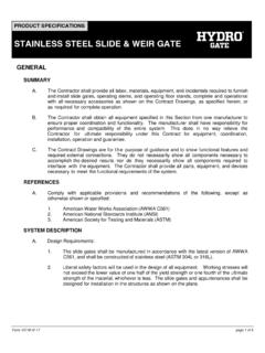
3 Reinforcing ribs (both horizontal and vertical) are cast integrally along with bosses for the seating faces are attached as described in the previous section for GATES24" HEAVY DUTY flap GATEAPPLICATIONS Flood Control Municipal Projects Farm Levees Sewer Outfalls Industrial Waste Lines Water and Sewage Treatment Plants Tidal Drainage Irrigation Systems Pump Discharge Control1 DescriptionDOUBLE-HINGE ACTIONFor proper seating of a flap gate , double-hinge action is necessary. The main hinge action on any flap gate is about its upper pivot points. However, flexibility is required at the bottom pivot points to allow seating of the flap against the seat. All Hydro gate flap GATES have this double action with bushings at each pivot is necessary that bottom hinge action be limited. Otherwise, the flap can turn completely over on itself and wedge back in the opening of the gate seat, rendering the gate useless.
4 Heavy-duty circular opening flap GATES are provided with hinge arms extending beyond the bottom pivot point. This limits the double-hinge action and prevents the flap from being rotated outward at the bottom. In addition, the bottom end of each hinge arm has a fine adjustment bolt to further limit the double-hinge action. Square or rectangular opening flap GATES are also provided with extended links for fine adjustment even though the bottom of the flap cannot be turned into the gate opening as in the round OF PIVOT POINTSL ubrication of pivot points on flap GATES is usually not necessary. The construction of the hinge assembly permits only a few degrees of rotation at the bottom pivot points. The gate cover rotates about the upper pivot points through an arc of 90 or less. With this limited rotation, lubrication of bushings is usually not justified nor is it normally recommended. When lubrication of flap gate pivot points is desired, two methods can be used:1.
5 A permanently lubricated bushing is installed at the factory. If lubrication of pivot points is desired, the permanently lubricated bronze bushing is recommended; or2. Links or hinge arms can be drilled for zerk-type grease fittings for use with ordinary grease OF HEAD THROUGH flap GATEST ests conducted on flap GATES show that the loss of head due to the flap riding on the water is very small compared with other losses in the hydraulic structure. Of these head losses, the entrance loss is usually considerably more critical than loss at the flap gate on the outlet end of the Hydraulic Laboratory of the State University of Iowa conducted a series of tests to determine the amount of head lost by water discharging through Model 10C flap GATES (formerly Armco-Calco). The GATES 18, 24 and 30" in diameter were supplied from commercial following passage is excerpted from the report of Floyd A. Nagler, associate professor of mechanics and hydraulics, who supervised the tests.
6 Based on these experiments the following empirical formula was derived to express the loss in head through Calco GATES of varying sizes and with different velocities of flow:L = loss of head in feetv = velocity of flow through gate in feet per secondd = diameter of outlet in feete = base of natural logarithmsg = acceleration of gravity, 32 ft / sec / sec L = 4v2 e g d It may be concluded from these experiments that the Calco gate in its hydraulic characteristics is all that the manufacturers have claimed for it. The small loss in head obtained through these GATES demonstrates that their installation has little effect on the discharged capacity of drainage outlets. Heavy-duty flap GATES have heavier flaps or covers than the gate model tested. As a result, head losses through these GATES may be slightly more than those indicated by the TO CONCRETE WALL OR PIPE FLANGES ince flap GATES open when subjected to a back pressure, only a small unseating force is encountered.
7 When a flap gate is under face or seating head, the force of the water pushes against the cover and only the weight of the gate itself is on the attaching bolts or anchors. For this reason, fasteners are needed only to hold the gate on the wall or flange. There is no hydrostatic force tending to separate the gate from the wall or attaching a round heavy-duty flap gate to a pipe flange, the gate is partially drilled to match a 125 lb. ASME bolt circle with only a portion of the holes being used. The cost to full drill the gate seat, mate every hole in the flange, and furnish the additional corrosion-resistant bolts and install them is not must be installed perfectly flat. Any warpage of a flange is transferred to the gate seat, preventing the flap to seat properly, particularly at low differential head. (Perfectly flat is generally defined as within plus or minus 1/64" of a true theoretical flat plane.)
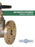
8 ( )( )2 ADJUSTABLE TOP PIVOT POINTSFor the adjustable pivot point on Hydro gate heavy-duty and medium-duty flap GATES , four holes are drilled and tapped two per side in the flat ears at the top of the gate seat (see Figure 6-1). Threaded studs are screwed into these holes and are securely locked in double-eared adjustable pivot lug is then placed on these two studs, and hex nuts are placed on both sides of the bosses. Another double set of ears projects to the top of the pivot lug for mounting of the hinge arms. A bushing in the hinge arm works on the body of the assembly pin. This arrangement allows the assembly pins through all pivot points to be in double shear for added strength and also provides for minimum lateral movement of the flap during gate the double-nut arrangement on each stud, the top pivot lug can be moved in and out from the wall to vary the location of the top pivot point with respect to the seating face of the gate .
9 All adjusting can be accomplished without removing the gate flap cover from the gate , as is necessary for other pivot force required to open the gate increases as the pivot lug is moved back toward the wall. When the gate is in a tidal zone or when the gate is partially submerged, the pivot lug can be moved back as far as possible so that the weight of the flap keeps the gate closed. Where less pressure is needed to operate the gate , the pivot lugs are moved farther away from the STEEL BUMPER (OPTIONAL) GATES mounted on a pump discharge pipe (not mounted on a head wall) or mounted in an area where excessive velocities occur should be specified to have a spring bumper (swing) to prevent the cover from being thrown over center over top of gate thus preventing the gate from closing automatically. It also prevents personal injury caused by a flap that is balanced or teetering over center. Designed for gate seat or wall mounting, depending on application or gate BARThe anti-sway bar creates a uniform and rigid hinging operation of the gate by tying together all four hinge points.
10 This prevents the gate components from shaking themselves loose and progression to through flap GATES decreases as head increases. At very low heads, there may be insufficient force to fully effect a tight, intimate fit of the seats, and somewhat greater leakage is PRESSUREAny significant depth of water behind the gate will cause the cover to unseat a crack and allow drainage. The pivot lug can be adjusted for more or less sensitivity. When adjusted for less sensitivity, greater depth of water (back pressure) will be needed to crack the gate open. Generally, flap GATES cannot hold more than a few inches of backwater for an extended length of NOTICEG ates (particularly smaller GATES ) in public areas should be fenced since children playing on or around them can lift the covers and be injured at the cover s pinch 6-1 ADJUSTABLE TOP PIVOT AND LINK ASSEMBLYP ivot Adjusting NutsAdjustable Pivot LugThreaded Adjusting StudsMounting HolesSeating FacePin BushingLink ArmCoverStainless Hinge PinStainless Pin WasherStainless Cotter PinLower Adjusting Mechanism3 HEAVY DUTY flap GATESD escriptionDESCRIPTIONFlat-back seats are for attaching the gate to a concrete wall pipe flange or wall thimble.