Transcription of FLEXmax Series Charge Controllers - outbackpower.com
1 FLEXmax Series Charge Controllers ( FLEXmax 80, FLEXmax 60). Owner's Manual About OutBack Power Technologies OutBack Power Technologies is a leader in advanced energy conversion technology. Our products include true sine wave inverter/chargers, maximum power point tracking Charge Controllers , and system communication components, as well as circuit breakers, batteries, accessories, and assembled systems. Contact Information Address: Corporate Headquarters European Office 17825 59th Avenue Hansastrasse 8. Suite B D-91126. Arlington, WA 98223 USA Schwabach, Germany Telephone: + + + (Technical Support) + (Fax). + (Fax). Email: Website: Disclaimer UNLESS SPECIFICALLY AGREED TO IN WRITING, OUTBACK POWER TECHNOLOGIES: (a) MAKES NO WARRANTY AS TO THE ACCURACY, SUFFICIENCY OR SUITABILITY OF ANY TECHNICAL. OR OTHER INFORMATION PROVIDED IN ITS MANUALS OR OTHER DOCUMENTATION. (b) ASSUMES NO RESPONSIBILITY OR LIABILITY FOR LOSS OR DAMAGE, WHETHER DIRECT, INDIRECT, CONSEQUENTIAL OR INCIDENTAL, WHICH MIGHT ARISE OUT OF THE USE OF SUCH INFORMATION.
2 THE. USE OF ANY SUCH INFORMATION WILL BE ENTIRELY AT THE USER'S RISK. Notice of Copyright FLEXmax Series Charge Controllers Owner's Manual July 2013 by OutBack Power Technologies. All Rights Reserved. Trademarks OutBack Power and the OutBack Power logo are trademarks owned and used by OutBack Power Technologies, Inc. The ALPHA logo and the phrase member of the Alpha Group are trademarks owned and used by Alpha Technologies Inc. These trademarks may be registered in the United States and other countries. Date and Revision July 2013, Revision C. Part Number 900-0009-01-00 Rev C. Table of Contents Introduction .. 5 Features .. 5 Firmware .. 5 Soft Keys .. 6 Installation .. 7 Standards and Requirements .. 7 Grounding .. 7 DC and Battery-Related Installation Requirements .. 7 Dimensions .. 8 Mounting the Charge controller .. 9 Wiring .. 10 Wire and Disconnect Sizing .. 10 FLEXmax 80 ..10 FLEXmax 60 ..10 Wiring 11 15 Power Up 15 Version and/or Voltage Setting 16 Status Screen.
3 17 End-of-Day Summary Screen .. 18 Navigating the End-of-Day Screens and Data Logging .. 19 Modes of Operation .. 20 Absorbing .. 20 Auto Start (Auto ReStart) .. 21 BatTmpErr .. 21 BatTooHot .. 21 Charged .. 21 EQ .. 21 EQ Done .. 21 EX-Absorb .. 22 Floating .. 22 GT Mode .. 22 High Voc .. 22 Low Light or Snoozing .. 22 MPPT Bulk .. 22 MPPT 22 MPPT EQ .. 23 New Voc .. 23 23 Over Temp .. 23 Re-Cal .. 23 Sleeping .. 23 Sys Error .. 23 Tracking .. 23 Unloaded .. 24 24 .. 24 Initial Operation .. 24 900-0009-01-00 Rev C 1. Table of Contents Changing the Settings on the FLEXmax .. 24 Accessing the Main Menu .. 24 Main Menu 25 Charger Screen ..26 Aux Screens ..27 AUX MODE Screen Vent Fan (AUX Mode) ..30 PV Trigger (AUX Mode) ..31 Error Output (AUX Mode) ..32 Night Light (AUX Mode) ..33 Float (AUX Mode) ..34 Diversion (AUX Mode)..35 Low Battery Disconnect (AUX Mode)..40 Remote (AUX Mode) ..41 Backlight ..41 EQ Battery Equalize.
4 42 Misc Advanced Snooze Mode (Advanced Menu) ..46 Wakeup Mode (Advanced Menu) ..47 MPPT Mode (Advanced Menu) ..47 Absorb Time Limits (Advanced Menu) ..49 Absorb End Amps (Advanced Menu)..49 Rebulk Voltage (Advanced Menu) ..50 Vbatt Calibration (Advanced Menu)..50 RTS Compensation (Advanced Menu)..50 Auto ReStart (Advanced Menu) ..52 Aux Polarity (Advanced Menu) ..53 Reset to Defaults? ..53 Logging ..54 Stats ..55 Viewing the Firmware Revision .. 56 Extended Play Mode .. 56 Rebooting the FLEXmax .. 57 MATE3 System Display and controller .. 59 Display and LED Status 59 Charge controller Soft DataLog Screen ..61 Graph Screens ..62 Menu Structure in the MATE3 .. 63 Charge controller Settings .. 64 Charger .. 64 64 Temperature Compensation .. 65 Battery Equalize .. 65 Grid-Tie 65 Auxiliary Output ( Charge controller ) .. 66 Aux Modes for the Charge controller ..66 Restart Mode ..67 Calibrate ..68 Reset Charge controller to Factory Device Data Logs.
5 69 Saving Data Logs for the FLEXmax Charge controller .. 69 Data Log File Format ..70 MATE/MATE2 Screens .. 71 2 900-0009-01-00 Rev C. Table of Contents Summary Screens .. 71 Status Screens .. 72 MODE Screens .. 72 METER Screens .. 73 SETPT Screens .. 74 LOG Screens .. 75 STAT Screens .. 76 Advanced Menus .. 77 Accessing the Advanced Menus .. 77 CHGR Menu .. 78 CC ADVANCED Menu .. 79 EQ 80 AUX 81 MATE and MATE2 Menu Maps for the FLEXmax .. 82 STATUS Menu Map .. 82 Advanced Menu Map .. 84 Menu Maps for the FLEXmax .. 87 Troubleshooting .. 91 Specifications .. 93 Electrical and Mechanical Specifications .. 93 Firmware Revision .. 93 Regulatory Specifications .. 93 Default Settings and 94 Applications .. 95 Maximum Power Point Tracking .. 95 Three-Stage Battery Charging .. 96 BULK .. 96 ABSORBING .. 97 97 Battery Temperature 97 Array Design .. 98 Sizing Guidelines .. 98 Open Circuit Voltage (Voc) .. 98 Weather Maximum-Power Voltage (Vmp).
6 99 Standard vs. Australian Default Settings .. 99 Hydroelectric and Fuel Cell Applications Performance Optimization .. 100 Auto Track Mode .. 100 U-Pick Mode .. 100 Grid-Interactive Settings .. 102 Charge controller Efficiency vs. Input Power .. 102 Definitions .. 103 Index .. 105 900-0009-01-00 Rev C 3. Table of Contents List of Tables Table 1 Battery Voltage and Charge 21 Table 2 Aux Mode 27 Table 3 Regulatory Specifications for All Models .. 93 Table 4 FLEXmax Settings .. 94 Table 5 Maximum PV Input Wattage per Charge controller .. 98 Table 6 Default Settings Standard vs. Australian .. 99 Table 7 Terms and Definitions .. 103 4 900-0009-01-00 Rev C. Introduction IMPORTANT: This manual provides safety guidelines and installation information for the FLEXmax Series Charge Controllers . It does not provide information about specific brands of PV modules and supplies limited information on batteries. Contact the supplier or manufacturer of the PV modules or batteries for additional information.
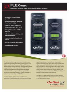
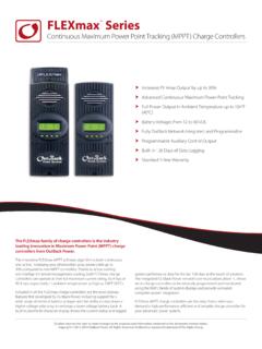
7 Thank you for purchasing a FLEXmax Series Charge controller (CC). These Charge Controllers offer an efficient, safe, multi-stage recharging process that prolongs battery life and assures peak performance from a PV array. Each Charge controller is designed to seamlessly integrate with other OutBack components and can be remotely monitored and configured (up to 1000 feet or 300 meters away) using the optional OutBack Power Technologies system displays. Features The FLEXmax Charge Controllers use continuous Maximum Power Point Tracking (MPPT), which seeks out the maximum power available from a PV array and uses it to recharge the batteries. Without this feature, the PV array does not operate at the ideal voltage and can only operate at the level of the battery voltage itself. (See page 95 for a description of MPPT.) Each Charge controller continuously tracks the array's maximum operating power. The FLEXmax Series has two models available: FLEXmax 80: 80 amps maximum continuous output current (up to 40 C without thermal derating).
8 FLEXmax 60: 60 amps maximum continuous output current (up to 40 C without thermal derating). Both models have the following features: Supports 12, 24, 36, 48, and 60 Vdc battery voltages Backlit LCD display screen with 80 characters (4 lines, 20 characters per line). Last 128 days of operational data are logged for review Voltage step-down capability allowing a higher PV array voltage configuration Manual and auto-equalize cycle Firmware This manual covers FLEXmax firmware revision 900-0009-01-00 Rev C 5. Introduction LCD Screen Soft Keys FLEXmax 80 FLEXmax 60. Figure 1 Charge controller Features Soft Keys Four soft keys are located directly below the LCD. The functions of the soft keys will vary depending on the location of the user within the menu structure. Some soft keys will be used for navigation. Some soft keys will be used for programming. Soft key functions are identified by text in the LCD screen directly above the key ( , EXIT).
9 In this manual, soft keys will be identified by brackets (for example, <EXIT>). Not every soft key may be used in some screens. Main Menu LCD. Charger Aux Light EQ Misc Advanced Logging Stats EXIT GO Soft Key Commands <EXIT>, <GO> etc. Soft Key Buttons SK1 SK2 SK3 SK4. Figure 2 Soft Keys 6 900-0009-01-00 Rev C. Installation Standards and Requirements All installations must comply with national and local electrical codes; professional installation is recommended. IMPORTANT: The Charge controller is designed for indoor installation or installation inside a weatherproof enclosure. It must not be exposed to rain and should be installed out of direct sunlight. Grounding This product is intended to be installed as part of a permanently grounded electrical system as shown in the wiring diagrams shown in Figure 6, Figure 7, and Figure 8. The FLEXmax equipment ground is marked with this symbol: The following important restrictions apply unless superseded by local or national codes: The negative battery conductor should be bonded to the grounding system at only one point in the system.
10 If a GFDI is present, the battery negative and ground are not bonded together directly but are connected together by the GFDI device when it is on. All negative conductor connections must be kept separate from the grounding conductor connections. The FLEXmax controller is not intended to be wired into a positive-ground configuration. However, certain telecom applications may require this configuration. If it is necessary to build a positive-ground system with OutBack products, contact OutBack Technical Support at + before proceeding. Additionally, consult the online forum at , where this subject has been discussed extensively. If damaged or malfunctioning, the FLEXmax should only be disassembled and repaired by a qualified service center. Please contact the local renewable energy dealer/installer for assistance. Incorrect reassembly risks malfunction, electric shock or fire. DC and Battery-Related Installation Requirements Shut off all DC circuit breakers before connecting any wiring.