Transcription of Flexural Fatigue and Ductility, Flexible Printed Wiring
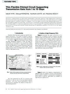
1 ScopeWith this test method the Flexural Fatigue life forany given bend radius, the Flexural Fatigue behavior and theductility of the conductor metal in percent deformation aftertensile failure can be :The indirect determination of conductor ductility byusing a Fatigue test is made necessary by the geometry anddimensions of foil samples which make tensile elongation andrupture tests inadequate for ductility Applicable DocumentsIPC-TM-650 Method , MicrosectioningIPC-TM-650 Method , Tensil Strength and Elongation,Copper FoilIPC-D-330 IPC Design Test test coupon shown in Figure 1 is the recommendedstandard test specimen pattern for either single- or double-sided Flexible Printed conductor width of the standard test pattern (Figure1) can be changed to determine line width.
2 Narrow conductor width will result in reduced flex livesdue to an increased flaw size/conductor width ratio. Wideconductors result in increased flex lives due to longer crackpropagation times and the possibility of strain relief due tocracks propagating in close proximity from opposite conduc-tor Flexible Printed Wiring product, whole or sectionsthereof, can be used if the circuit geometry is such that thelong dimension is at least mm [ inches], the widedimension no more than mm [ inches], and the con-ductors in the long direction can be electrically connected inseries to give a pattern similar to the standard test pattern (seeFigure 1). Flex Tester, Universal Mfg.
3 , Model FDF or 2 FDFor equivalent (see and Figure 2). cutter, punch or tensile cut router. Note tool capable of measuring mm[ inch]. , HP-67, Programmable Calculator holders, x mm [8 x 1/2 inch] of veryflexible material, , epoxy-impregnated glass cloth, paper, Preparation of the sample cutter to cut the mm [1/8 inch]wide test specimen. Examine each specimen for nicks, cuts,or curled edges. Discard any specimen with 1 Test coupon configuration (recommended)ttttttttttttt45327104mm[ ] [ "]NOTE [.150] (NOTE 1)NOTES:1. [.030"] Conductor width, [.030"] spacing2. Pattern on opposite circuit sides are identical3. 5-digit lot number of production [.]
4 100"] [.050"] [.050"] [ "]The Institute for Interconnecting and Packaging Electronic Circuits2215 Sanders Road Northbrook, IL 60062-6135 IPC-TM-650 TEST METHODS Fatigue and Ductility, Flexible PrintedWiringDate3/91 RevisionCOriginating Task GroupN/AMaterial in this Test Methods Manual was voluntarily established by Technical Committees of the IPC. This material is advisory onlyand its use or adaptation is entirely voluntary. IPC disclaims all liability of any kind as to the use, application, or adaptation of thismaterial. Users are also wholly responsible for protecting themselves against all claims or liabilities for patent referenced is for the convenience of the user and does not imply endorsement by the the micrometer to determine the specimen thick-ness, t, at the test region of the specimens to the mm [ inch].
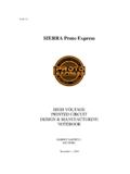
5 In the case of single-sided orcover-coated specimens, core thickness, tM, has to be deter-mined also (see Figure 2).Note:Thickness is a critical parameter in the determination offatigue ductility. A 10% error in tMresults in a 14% error in :For asymmetric configuration (2nd configuration in Fig-ure 2) the core thickness, tM, is preferably determined as afraction of the specimen thickness, t, from a microsection pre-pared per IPC-TM-650, Method , and measured with ametallurgical microscope at 200X minimum with a suitable filareyepiece or reticle. The measurement is to be made from thevalley of the rough surface to the smooth surface or valley tovalley where both surfaces are rough.
6 The tMis to be madeonce on a batch or lot basis, and this fractional value of tM/t isthen multiplied by all other micrometer, t, values to achievecore values for all samples. This applies only to the secondand third configuration in Figure 2, where tMcannot be deter-mined by a standard test coupons, connect the meander pat-terns on opposite circuit sides in series and attach thin relayleads to the free ends of the meander patterns. For nonstand-ard test specimens, connect all conductors to be tested andmonitored in series and attach thin relay leads to the two test specimen to the ends of 2 sample holderswith adhesive tape and clamp 224 grams [8 ounces] circuitweight to free ends of sample holders to form a loop (see Fig-ure 3).
7 Note:For Flexural Fatigue tests lasting in excess of 1000cycles, the adhesive tape attachment needs to be substantialenough to prevent relative sliding of specimen and sampleholder as a result of the cyclic flexure Test mandrels to flex tester, adjust the support rollerpositions for a clearance of mm [ inches] (shim pro-vided) between rollers and :For the ductility test, it is important that the specimensfail between 30 and 500 cycles. Suggested mandrel diam-eters are mm [ inch] for double-sided circuitry mm [ inch] for single-sided circuitry, but for somesamples, mandrel diameters different from these diametersmay be necessary. Larger mandrel diameters result in longercyclic life and smaller diameters in shorter 2 Minimum core thicknesstCOVERCOATCOVERCOATttMttttttMtt tttt = tMSUBSTRATECONDUCTORCONDUCTORSUBSTRATECO NDUCTORCONDUCTORCONDUCTORSUBSTRATEIPC-24 21-2 Figure 3 Fatigue ductility flex Fatigue and Ductility, Flexible Printed WiringDate3 test specimen between mandrels, plug relayleads into relay jacks, set counter to zero, and start flex discontinuity constitutes failure and the flextester stops cycles-to-failure indicated on Ductility the ductility for each specimen by itera-tively solving the formula below:Nf + [exp(Df) ]( log105Nf) 2tM21+t=0where.
8 Df= Fatigue ductility, inch/inch (x100,%)Nf= cycles-to-failureSu= ultimate tensile strength, psiE = modulus of elasticity, psitM= core thickness, incht = specimen micrometer thickness, inch = mandrel radius of curvature, within mm [ ]Note:This formula is exact only for symmetric cross the case of nonsymmetrical single-sided laminate, theuncertainty of the location of the neutral axis introduces someerror. The error in D, is kept below 20% if[ttM 1]2 EsubstrateE Design Guide, IPC-D-330, Section 6, Flexibility Consid-erations in Design of Flexible Printed Wiring , gives moredetailed information for the accurate determination of the loca-tion of the neutral axis and the cyclic :Determine Suas per IPC-TM-650, Method E during the test for Suby unloading and reloadingafter about 2% elongation and measuring the slope of thereloading.
9 The calculator program described in paragraph the ductility formula and conveniently prompts for allnecessary input the average product ductility from at leastthree Fatigue TestThe number of cycles-to-failure, is theflexural Fatigue life in fully reversed bending for the bend radiuscorresponding to the radius (1/2 diameter) of the test mandrelused. An average Flexural life from at least three specimensshould be Fatigue BehaviorThe Fatigue behavior of a samplecan be obtained by determining the Flexural Fatigue life with anumber of different diameter mandrels. Plotting the results ina strain range versus Fatigue life Manson-Coffin plot log =[2tM/(2t + t)] versus log Nf) allows intra- and extrapolation toother bend radii or Fatigue Flexural Fatigue life at bend radii other than themandrel radius can also be obtained by evaluating the ductil-ity formula for the flex life in cycles-to-failure using the productductility determined in and the desired bend further technical details, reference the mate-rial shown in paragraph , W.
10 , Fatigue Ductility for Foils and FlexiblePrinted Wiring . Program No. 1883D HP-67/97 User sLibrary, Hewlett Packard Co., Corvallis, Oregon, , W., Fatigue Ductility Flex Tester, DrawingL520163, Bell Telephone Laboratories, Inc., Whippany, NewJersey, Test Equipment SourcesThe equipment sourcesdescribed below represent those currently known to theindustry. Users of this test method are urged to submit addi-tional source names as they become available, so that this listcan be kept as current as Ductility Flex Tester, Universal Mfg. Co., Inc.,1168 Grove St., Irvington, NJ 07111; Precision Sample Cutter Model JDC 125-N Fatigue and Ductility, Flexible Printed WiringDate3/91 RevisionCPage3of3