Transcription of Flight Management Systems - davi.ws
1 2001 by CRC Press LLC 15 Flight Management Systems Int roduction Fundamentals Navigation Flight Planning Trajectory Predictions Performance Computations Guidance Auto Flight Phase Transitions Summary Introduction The Flight Management system typically consists of two units, a computer unit and a control display computer unit can be a standalone unit providing both the computing platform and various interfacesto other avionics or it can be integrated as a function on a hardware platform such as an IntegratedModular Avionics cabinet (IMA).
2 The Control Display Unit (CDU or MCDU) provides the primaryhuman/machine interface for data entry and information display. Since hardware and interface imple-mentations of Flight Management Systems can vary substantially, this discussion will focus on the functionalaspects of the Flight Management Flight Management system provides the primary navigation, Flight planning, and optimized routedetermination and en route guidance for the aircraft and is typically comprised of the following interrelatedfunctions.
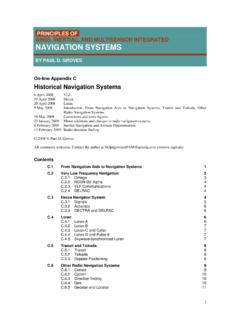
3 Navigation, Flight planning, trajectory prediction, performance computations, and accomplish these functions the Flight Management system must interface with several other avionicssystems. As mentioned above, the implementations of these interfaces can vary widely depending uponthe vintage of equipment on the aircraft but generally will fall into the following generic categories. Navigation sensors and radios Inertial/attitude reference Systems Navigation radios Air data Systems Displays Primary Flight and navigation Multifunction Engine Flight control system Engine and fuel system Data link system Surveillance systemsFigure depicts a typical interface block diagram.
4 Randy Walter Smiths Industries 2001 by CRC Press LLC Today, Flight Management Systems can vary significantly in levels of capability because of the variousaviation markets they are intended to serve. These range from simple point to point lateral navigatorsto the more sophisticated multisensor navigation, optimized four-dimensional Flight planning/guidancesystems. The Flight Management system in its simplest form will slowly diminish as reduced separationairspace standards place more demands on the aircraft s ability to manage its trajectory more accurately,even though lateral-only navigators will continue to have a place in recreational general its current role in the aircraft, the Flight Management system becomes a primary player in thecurrent and future CNS/ATM environment.
5 Navigation within RNP airspace, data-linked clearances andweather, aircraft trajectory-based traffic Management , time navigation for aircraft flow control, and seam-less low-visibility approach guidance all are enabled through advanced Flight Management functionality. Fundamentals At the center of the FMS functionality is the Flight plan construction and subsequent construction of thefour-dimensional aircraft trajectory defined by the specified Flight plan legs and constraints and the aircraftperformance. Flight plan and trajectory prediction work together to produce the four-dimensional tra-jectory and consolidate all the relevant trajectory information into a Flight plan/profile buffer.
6 Thenavigation function provides the dynamic current aircraft state to the other functions. The vertical, lateralsteering, and performance advisory functions use the current aircraft state from navigation and theinformation in the Flight plan/profile buffer to provide guidance, reference, and advisory informationrelative to the defined trajectory and aircraft state. The navigation function responsible for determining the best estimate of the current state ofthe aircraft. The Flight planning function allows the crew to establish a specific routing for the aircraft.
7 FIGURE Typical interface block ManagementAltitude, speeds,temperaturesInitial positionTuning cmdsFreq, range, bearing, LOCdeviation, GPS position,GPS ground speed, timeNavigationReceiversData LinkMCDUA ircraftDisplaysFlightControlsSurveillanc eSystemsEngine andFuelSystemsAir DataPosition, velocities, vert spd, pitch, roll,heading, accelsInit data,flt plans,clearance,weatherEntered dataDisplay dataMap scale,display selectionsFlt plan & path,nav data, routedata, HSI dataTactical cmds,modesRoll axis cmds,pitch axis cmds,thrust axis cmdsTrajectoryconflictsFlight ID,Aircraft state,trajectoryFuel weight,eng thrustThrust limitsInertialReference 2001 by CRC Press LLC The trajectory prediction function responsible for computing the predicted aircraft profilealong the entire specified routing.
8 The performance function provides the crew with aircraft unique performance informationsuch as takeoff speeds, altitude capability, and profile optimization advisories. The guidance functions responsible for producing commands to guide the aircraft along boththe lateral and vertical computed on the particular implementation, the ancillary I/O, BITE, and control display functionsmay be included as well. Since the ancillary functions can vary significantly, this discussion will focus onthe core Flight Management are typically two loadable databases that support the core Flight Management functions.
9 These arethe navigation database which must be updated on a monthly cycle and the performance database that onlygets updated if there s been a change in the aircraft performance characteristics ( , engine variants orstructural variants affecting the drag of the aircraft).The navigation database contains published data relating to airports, navaids, named waypoints, airwaysand terminal area procedures along with RNP values specified for the associated airspace. The purpose ofthe navigation data base is twofold. It provides the navigation function location, frequency, elevation, andclass information for the various ground-based radio navigation Systems .
10 This information is necessaryto select, auto-tune, and process the data from the navigation radios (distance, bearing, or path deviation)into an aircraft position. It also provides the Flight plan function with airport, airport-specific arrival,departure, and approach procedures (predefined strings of terminal area waypoints), airways (predefinedenroute waypoint strings), and named waypoint information that allows for rapid route construction. Adetailed description of the actual data content and format can be found in ARINC performance database contains aircraft/engine model data consisting of drag, thrust, fuel flow,speed/altitude envelope, thrust limits, and a variety of optimized and tactical speed schedules that are uniqueto the aircraft.