Transcription of Float switch For the process industry, lateral ...
1 Level A division of the WIKA groupFloat switchFor the process industry, lateral installation with external chamberModel ELSData sheets showing similar products: Float switch ; model FLS; see data sheet LM switch , horizontal installation; model HLS; see data sheet LM switch with external chamber, model ELS-AApplications Mounting on engines, tanks, vessels or enclosures, where, due to a lack of space, installation within them is not possible Use for turbulent liquid levels such as in oil sumps in large engines, gearboxes etc. Pump and level control and monitoring of distinct filling levels Chemical, petrochemical industry, natural gas, offshore, shipbuilding, machine building, power generating equipment, power plants process water and drinking water treatmentSpecial features Freely selectable switch position through fixing the Float switch at the required level Large range of application due to the simple, proven functional principle For harsh operating conditions, long service life Operating limits:- Operating temperature:T = -30.
2 +150 C- Operating pressure:P = Vacuum up to 40 bar- Limit density: 600 kg/m3 DescriptionIn an external chamber (bypass chamber), a Float with a permanent magnet moves on a guide tube in relation to the liquid level, following the principle of communicating vessels. Within the guide tube is fitted a reed contact (inert gas contact), which is energised, through the non-magnetic walls of the Float and guide tube, by the approach of the Float magnet. By using a magnet and reed contact the switching operation is non-contact, free from wear and needs no power supply. The contacts are data sheet LM 1 of 7 KSR data sheet LM 10/2018 The switching functions always refer to a rising liquid Float switch is simple to mount and maintenance-free, so the costs of mounting, commissioning and operation are further approvals see page 2 Further special features Guide tube from stainless steel Float from stainless steel , titanium or Buna (NBR) External chamber from aluminium AlMg5, red bronze Rg5 or stainless steel Universal signal processing.
3 Connection direct to a PLC is possible, NAMUR connec-tion, signal amplification / contact protection relays Works independently of foaming, conductivity, dielectricity, pressure, vacuum, temperature, vapours, condensation, bubble formation, boiling effects and vibrations Maximally one change-over contact Float switches qualify as simple apparatus in accordance with EN 60079-11 section and can be installed in zone 1 hazardous areas without certification, so long as the equipment is operated in a certified intrinsically safe circuit with a minimum explosion protection of Ex overview Model ELS-A (ABAU):Version with external chamber from aluminium Model ELS-B (ABRU):Version with external chamber from red bronze Model ELS-S (ABVU):Version with external chamber from stainless steelApprovalsLogoDescriptionCountryEU declaration of conformity Low voltage directive RoHS directiveEuropean UnionEACEMC directive and low voltage directiveNo.
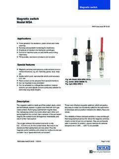
4 RU Д Economic CommunityDNV GLShips, shipbuilding ( offshore)No. TAA00001 YKInternationalBureau VeritasShips, shipbuildingNo. 30168/B0 BVInternationalApprovals and certificates, see websitePage 2 of 7 KSR data sheet LM 10/2018 Float switch , version with external chamber from aluminiumModel ELS-AGuide tube from stainless steel housingExternal chamberDrain plug G " switch positionModel ELS-AExternal chamberAluminium AlMg5 Electrical connectionConnection housing, aluminium 64 x 58 x 34 mmCable entry in the direction of the process connection (other alignment on request) process connectionCompression fitting with ferrule GE10-LR, galvanised steel (other sizes on request)Max. operating pressure1 barSpecial version: 6 barGuide tubeMaterial: Stainless steel : 12 mmFloatMaterial: Stainless steel , Buna (NBR) or titanium diameter: 40.
5 52 mmFloat selection depending on process conditions (see page 6)Temperature range-30 .. +150 CSwitching functionChange-overSwitch position fixed (centred, see drawing)Max. number of contacts1 change-overSwitching power, change-overAC 230 V; 40 VA; 1 ADC 230 V; 20 W; AMounting positionVertical 30 Ingress protectionIP65 per IEC/EN 60529 Page 3 of 7 KSR data sheet LM 10/2018 Float switch , version with external chamber from red bronzeModel ELS-BGuide tube from stainless steel housingExternal chamberDrain plug G " switch positionModel ELS-BExternal chamberRed bronze Rg5 Electrical connectionConnection housing, aluminium 64 x 58 x 34 mmCable entry in the direction of the process connection (other alignment on request) process connectionCompression fitting with ferrule GE10-LR, brass (other sizes on request)Max.
6 Operating pressure6 barGuide tubeMaterial: Stainless steel : 12 mmFloatMaterial: Stainless steel , Buna (NBR) or titanium diameter: 40 .. 52 mmFloat selection depending on process conditions (see page 6)Temperature range-30 .. +150 CSwitching functionChange-overSwitch position fixed (centred, see drawing)Max. number of contacts1 change-overSwitching power, change-overAC 230 V; 40 VA; 1 ADC 230 V; 20 W; AMounting positionVertical 30 Ingress protectionIP65 per IEC/EN 60529 Page 4 of 7 KSR data sheet LM 10/2018 Float switch , version with external chamber from stainless steelModel ELS-SGuide tube from stainless steel housingExternal chamberDrain plug G " switch positionModel ELS-SExternal chamberStainless steel connectionConnection housing, aluminium 64 x 58 x 34 mmCable entry in the direction of the process connection (other alignment on request) process connection Flange connection Threaded nipple Threaded bushing Compression fitting with ferrule GE10-LR, stainless steel (other sizes on request)Max.
7 Operating pressureChamber end top 100 = 1 barChamber end top 130 = 40 barThe maximum pressure is also limited by the tubeMaterial: Stainless steel : 12 mmFloatMaterial: Stainless steel , Buna (NBR) or titanium diameter: 40 .. 52 mmFloat selection depending on process conditions (see page 6)Temperature range-30 .. +150 CSwitching functionChange-overSwitch position fixed (centred, see drawing)Max. number of contacts1 change-overSwitching power, change-overAC 230 V; 40 VA; 1 ADC 230 V; 20 W; AMounting positionVertical 30 Ingress protectionIP65 per IEC/EN 6052930M = 55135L1 = 98L1 = 143 Page 5 of 7 KSR data sheet LM 10/2018 MaterialVersionSuits guide tube in mm Ain mmBin mm Cin mmMax. operating pressure in barMax. operating temp. in CLimit density 85 % in kg/m3 Order steel = Limit density of the medium, immersed Float volume 85 %E = Nominal density of the medium, immersed Float volume 50 % A CDEBS pherical floatNote: The optimum Float will be selected after a feasibility test carried out by floatD = Limit density of the medium, immersed Float volume 85 %E = Nominal density of the medium, immersed Float volume 50 % CDEB AMaterialVersionSuits guide tube in mm Ain mmBin mm Cin mmMax.
8 Operating pressure in barMax. operating temp. in CLimit density 85 % in kg/m3 Order steel (NBR)B40A124030153805809728 Page 6 of 7 KSR data sheet LM 10/2018 KSR KUEBLER Niveau-Messtechnik AGHeinrich-Kuebler-Platz 169439 Zwingenberg/GermanyTel. +49 6263/87-0 Fax +49 A division of the WIKA group 01/2010 KSR KUEBLER Niveau-Messtechnik AG, all rights specifications given in this document represent the state of engineering at the time of reserve the right to make modifications to the specifications and informationTo order the described product the order number (if available) is :Model / External chamber material / Number of change-over contacts / OptionsAC 24 .. 230 VRS1 CDC 24 .. 250 VS1+ PLCS1 RSC1+ DC 24 VInductive loadAC voltageInductive loadDC voltageCapacitive loadRC elementCapacitanceResistanceVoltageOrder F470 OhmAC 115 V110446B3 F1,000 OhmAC 230 V110460 Contact protection measuresThe reed contacts should be protected against any voltage or current spikes that might on the different load types different protective circuits are protection relaysContactsInputPower supplyApproval numberOrder x change-over AC 250 V, 2 A2 x contactsDC 20.
9 30 x change-over AC 253 V, 2 A2 x contactsDC 20 .. 30 VII 1 GD EEx ia IICPTB 02 ATEX x change-over AC 250 V, 2 A2 x contactsAC 230 x change-over AC 253 V, 2 A2 x contactsAC 230 VII 1 GD EEx ia IICPTB 02 ATEX 2073112943 Model element10/2018 ENPage 7 of 7 KSR data sheet LM 10/2018