Transcription of Floor Drain Technical Data
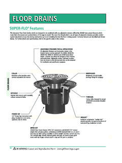
1 Used As Anchor FlangeIn One Pour SlabFINISHED FLOORUsed As Flashing FlangeWaterproof MembraneRemovable Flashing CollarGrate will not tilt out ofdrain body when heavymoving loads pass over SETTRACTOR GRATE"SAFE-SET" BUCKET AND GRATEB ucket Must Be In Place Before Grate Is ReplacedAdditional Perimeter Drainage OpeningsAfter the top size and anticipated flow are determined by the Design Professional, thefollowing points shall be taken into consideration when selecting the Floor of Grate or Cover (Based on Anticipated Traffic) ASME (FloorDrains) ratings are as follows. These are static lioad ratings and do not take into con-sideration impact or dynamic loading. These load ratings are general catagories andare provided for guide purposes only. The Design Professional shall contact the fac-tory for unusual applications, where conditions of use, load concentration, installa-tions, etc.
2 , can affect results and ASME (Formerly ANSI ): LIGHT DUTY: All grates/covers having a safe live load under 2,000 lbs. (900 KG). MEDIUM DUTY: All grates/covers having a safe live load between 2,000 lbs. (900KG) and 4,999 lbs. (2250 KG). HEAVY DUTY: All grates/covers having a safe live load between 5,000 lbs. (2250KG) and 7,499 lbs. (3375 KG). EXTRA HEAVY DUTY: All grates/covers having a safe live load between 7,500 lbs.(3375) and 10,000 lbs. (4500 KG). SPECIAL DUTY: When the grate safe live load is greater than 10,000 lbs. (4,500KG).After the weight capacity is established, a suitable Drain can be IS THE RESPONSIBILITY OF THE DESIGN PROFESSIONAL TO CONTACT THEFACTORY AND OBTAIN SPECIFIC LOAD RATINGS FOR EACH SPECIFIC DRAINWHETHER IT IS A STANDARD OR UNUSUAL of Top Material (Unfinished Areas) Drains located in heavy traffic areasshould be specified with heavy duty cast iron grates.
3 In areas where shock loads areanticipated, a ductile iron grate should be specified in lieu of the cast iron grate. (Finished Areas) Most drains are available with nickel bronze or bronze tops to matchthe surrounding trim in finished areas. Usually finished areas require light duty ormedium duty tops.(Finished Areas with Increased Load) Many finished Floor areas are subject toincreased loadings. Examples are convention centers, equipment showrooms andindustrial plants. Heavy duty cast iron tractor grates SHALL be specified with bronzeor nickel bronze veneered tops. Top Shape Round, square or rectangular styles are available to blend with all typesof construction and Floor patterns. The round top is the most flexible type since it canbe easily oriented to most Floor Selection Body depth is proportioned to the top size.
4 Many Smith Floor drainscan be specified with various body depths. The deeper body is desirable when unusu-ally large amounts of water are to be drained or an extra large sediment bucket isrequired. Most Floor Drain bodies are available with a flange for either anchoring the Drain in thefloor slab or for use as a flashing flange in upper floors and waterproofed areas. ManySmith drains are regularly furnished with a flanged body and a combination "top flash-ing collar" which can be used to clamp the waterproof TO SELECT A Floor DRAINF loor drains are primarily used for inside locations where the flow rate intothe Drain can be anticipated. Sufficient top size and grate free area to passthe anticipated flow are required. Grate free area is defined as "the total areaof the drainage openings in the grate." The Drain outlet should be sized largeenough to safely discharge the maximum flow through the grate without cre-ating water build-up (ponding).
5 The Design Professional shall determine therequired flow and Location For most indoor locations, the grate free area shouldbe 1 1/2 times the transverse area of the connecting pipe. See Table 1. Thenumber and location of drains are determined by the Design Professionalbased on the configuration of the Floor plan, type of operation,location ofequipment and other factors known to the Design used to Drain small exterior areas, area drains should have an openarea equal to twice the transverse area of the connecting pipe. See Table Design Professional shall determine whether the the 2 to 1 ratio issufficient or if exterior surface flow calculations are Grate Free Areas for Various Outlet Pipe Sizes 1 1 Maximum Nominal Transverse Flow Requirements Flow Requirements Pipe Size, Area of Pipe, (Interior Areas) (Exterior Areas) IN SQ IN SQ IN SQ INSELECTING THE DRAINFLOOR DRAINSTECHNICAL DATAT able 1 CUSTOMERDRIVENSMITH PREFIX DX WIDE FLANGE BODY DRAINSThe Prefix DX designates a wide flange that can be furnished on certain Smith floordrains.
6 This flange receives the membranes and coatings of a waterproof Floor cov-ering system. These coverings are thin coatings which are installed in a series oftrowel coats. The covering forms its own membrane, flashing and durable trafficsurface. The wide flange is regularly furnished 4" wide. The usual covering isapproximately 3/16" thick and may be applied over many subsurfaces such as con-crete, gypsum or wood decks. This type of covering is particularly adaptable to flatroofs which are used for recreational purposes, balconies, area ways, plazas, sundecks, floors and a DX flange is required on drains other than those shown in this section, theprefix DX must be used with the figure number. The flange will be 4" wide (mini-mum) with a 3/16" lip regularly furnished.
7 If the waterproof deck covering is greateror less than 3/16", the lip dimension must be specified or the Drain has to be set atthe proper elevation by the plumbing contractor to compensate for these differ-ences. Roughing dimensions of the body must be adjusted accordingly. Drain bodyshould be set low enough to permit "dimpling" of the area surrounding the VARIATIONSSome job applications require drains with buckets to intercept and collect debrissuch as solid objects and leaves so the waste system is protected. Smith engineershave designed various types of buckets for different applications to accomplish thispurpose. NOTE:Where a bucket is not available, a dome bottom strainer or flatbottom strainer may be used to protect the waste SUSPENDED BUCKET WITH PORTED OPENINGSThis bucket is ideal for drains which are located in areaswhere a large amount of debris is anticipated.
8 It is partic-ularly useful in areas such as vegetable storeroomswhere vegetables are pre-cleaned and a considerableamount of leaves and stalks are washed into the solid bottom of this bucket retains this type of solidmatter while the overflow is discharged through thescreens in the top of the SUSPENDED SLOTTED BUCKETUsed where large leafy objects such as peelings, leavesand paper are to be intercepted. When wetted down,these types of solids will compact at the bottom of thebucket. Slots run completely up the sides of the bucket tooffer complete drainage even when the bottom section isfilled with FREE STANDING BUCKETUsed where heavy materials such as sand, stones andchips are to be intercepted and separated from thedrainage water. When sand laden drainage water entersthe bucket, the sand falls to the bottom and the clearwater flows over the top of the bucket into the waste line.
9 Drain GASKET INSTALLATION DATAJay R. Smith Speedi-Seal (Fig. 9502) and Speedi-Set (L) gaskets are available foruse with cast iron, plastic, steel or glass pipe. Installation of your Floor drains usingSpeedi-Seal or Speedi-Set can represent a significant reduction in time and laborcosts over conventional caulk or NO-HUB GASKET WITH FIG. 9239 CAULK SUPPORT STRAPThe caulk support strap eliminates the need to search for supports for the Drain dur-ing the caulking operation and the need to purchase expensive riser clamps. Itsunique design allows it to be used on 2, 3 or 4" service weight or extra heavy installer secures the strap in place, lubricates the plain end of the spigot, thenrests the inside caulk outlet Drain on the caulk support strap. The strap supports thedrain body weight and the force created by the caulking operation without inside surface of the Speedi-Seal gasket is then lubricated, pressed in placedown over the pipe and lightly tapped until flush with the top of the pipe.
10 Installationis fast and simple and the caulk support strap may be left in place or OUTLET TYPE LSpeedi-Set drains are available with most bottom outlet models by specifying (L) andpiping material used. Service weight (SW) is regularly furnished or specify extra heavy(LXH). The Speedi-Set joint consists of a NO-HUB outlet body and a factory insertedextra heavy or service weight Speedi-Set neoprene gasket. The installer simply lubri-cates the plain end of the spigot and the inside of the gasket, then presses the drainbody down over the pipe until contact is made with the internal stop of the gasket. Theinstallation eliminates the need for hot lead, caulking irons, NO-HUB clamps, CHART FOR SPEEDI-SEAL AND SPEEDI-SET GASKETSOPTIONAL VARIATIONSV ariations to meet particular job requirements are available. The illustrations shown below are some of the more common -BSediment BucketSuffix -DDome GrateSuffix -H Hinged Grate Allows quick access to theline and assures replacementof -P Trap Primer Connection-P050 (1/2") RegularlyFurnished, -P075 (3/4")available on -SSquare TopSuffix -UVandal Proof ScrewsREGULARLYFURNISHED:Flat Head Socket OD TOLERANCE RANGEGASKET-PIPE COMPATIBILITYNOM.