Transcription of Floor load Handbook - TAB
1 Floor load Handbook CompaCt mobile File system (CmFs)Professional Services Filing Systems Technology Solutions Storage SystemsTITLEOFFICEREPTAB Products DESIGNS REPRESENTED BY DRAWING ARE CONFIDENTIAL AND SHOULD NOT BE DISCLOSED WITHOUT WRITTEN PERMISSION FROM TAB. S8S8S3S4S6S2S8S2S8S8S4S8S8S8S6S8S8S8S8S3 S6S8S8S1S8S8S8S8S8S8S8S34'2 3/4"3'4 1/2"4'2 3/4"1'9 3/4"20'0"12'8 1/4"introductionA compact mobile file system (CMFS) consists of shelving (and/or cabinets) mounted on moveable carriages that roll on fixed tracks so that only one aisle space is required for several rows of shelving. Compact mobile file systems are used to store paper media of all varieties, (records, files, documents, books, maps, xray films, motion picture films, artifacts, etc.) Compact mobile file systems significantly increase the available storage capacity when compared to static file systems.
2 Consequently, Floor loading may increase beyond the normal Floor design live Handbook is written for the professional licensed architects and engineers who will review the Floor system and determine its ability to safely support the CMFS. TAB Products Co. will not determine if a high density mobile storage system can be installed on a particular Floor since this is the responsibility of the architect and structural engineers of record. TAB has provided example calculations, diagrams, and useful charts. TAB will also provide suggestions and alternatives in order to successfully resolve a Floor loading problem if one considering placing a CMFS on a structural Floor (composed of slabs, beams, and girders) the architect or engineer of record should consider the entire structural Floor assembly. Most CMFS are relatively small and can be installed on structural floors without retrofitting the existing structure.
3 For existing buildings, additional structural support, if required, will be more economical if the support beams are installed above the slab. For buildings being designed or being built, the addition of beams under the tracks and beams and girder reinforcement , if required, should occur below the structural Floor system has to be reviewed for both stress and deflection. A CMFS is very sensitive to Floor deflection. The ball bearing housed wheels will move by gravity if the Floor deflects significantly after the system is loaded. This carriage movement is called drifting. Therefore, to help eliminate drifting, it is important for the design professional to use realistic loads in order to determine Floor deflection. This guideline will address the various aspects of the design so that the design professional can successfully place a CMFS on a structural entire weight of the CMFS is supported by continuous tracks which in turn are supported by the structure.
4 These track line loads can be large see the Track Loading Chart on page 6. The use of average load per square foot or an equivalent uniform load may yield erroneous results. Nominal beams or plates above the Floor can be used to support the track forces to the supporting Floor beams for existing buildings. Some concrete framed slabs may not need any additional supports (concrete flat slabs, flat plates, waffle slabs, etc.) For design purposes, no live load occurs between the CMFS tracks. When considering an open aisle within the CMFS, a realistic live load for this aisle is to place a 200 pound person in front of each shelving cabinet, 200 lbs/3ft. of carriage open aisle live load is = 200lbs 3ft. x 3ft. = 22lbs/sq. previously stated, the use of an equivalent uniform live load is not appropriate for a CMFS due to the large track forces. Slabs and individual beams can easily be overstressed or deflect so that mobile file carriages can drift.
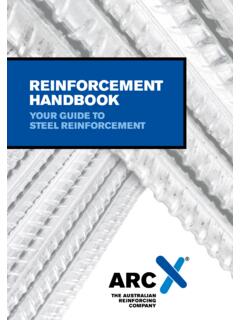
5 An equivalent uniform live loading may be appropriate when a CMFS is located on a concrete flat slab or flat plate or other heavily designed concrete Floor systems. Since a CMFS is a real load, shear stresses and Floor deflection for concrete flat plates should be loads^2 Floor GIRDERFLOOR GIRDERCOLUMNCOMPACT MOBILEFILING SYSTEMLOCATION ALOCATION BLOCATION CLOCATION DFLOORBEAMFLOORBEAMFLOOR PLAN locationThe optimum location for a CMFS is to be located over or adjacent to a girder or beams adjacent to a column. See Figure 1 and Floor Plan. Location A is optimum, spreading the loads on 2 girders and at the ends of the Floor beams. Location B, the next most favorable position, puts all the load on one girder and at the ends of the Floor beams. Location C puts all the load near the ends of the Floor beams. At location D, the CMFS will induce maximum bending stress and deflection of the Floor beams.
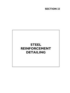
6 Location D should be avoided if 1 The ideal track orientation is perpendicular to the Floor beams (or joists) or, where the Floor beams are spaced 6 ft. or less, then directly over the Floor beams. If the tracks are parallel to the Floor beams, secondary framing may be required if the Floor slab is structurally inadequate to support the track line loads. TAB Products Co. can space the tracks at any spacing requirement up to a maximum of 7 ft 2 in. If at all possible, locate a track directly over a girder or Floor beam. This may eliminate a track support orientation3 ABCDNote: For all of the examples shown in Figure 1, the file orientation can be rotated 90 . See Track Orientation BEAMSECONDARY TRACK BEAMTRACKDECKINGFLOORSLABTRACKS & TRACK BEAMSTRACK BEAMSFLOOR BEAMSASECONDARY BEAMSSUPPORTINGF loor Plan - tracks parallel and offset from Floor beamsFLOOR SLABHANDICAP RAMPASECTIONFLOOR BEAMTRACK & TRACK BEAMSECONDARY BEAMDECKINGP lacing track support beams in the same depth as the track beams will bedifficult due to building access.
7 All material has to be put into standardelevators and taken through corridors and doorways. Welding on siteshould be avoided if possible. All connections should be bolted. FLOORBEAMMost CMFS systems can be rotated 90 , especially if the system is within an open landscaped office area. The rotated system may have a completely new configuration (number of carriages and/or carriage length). One of the main reasons for rotating a system is to place the tracks perpendicular to the Floor beams and eliminate secondary beams to support the track beams. This will lower the CMFS decking height above the Floor and reduce the ramp length. See Figure 2 Handicap accessADA requires that all office functions have to be accessible to the handicapped. This ruling required the construction of the handicap ramps (maximum slope of 1:12). Long handicap ramps typically are difficult to install due to the amount of space they use.
8 The handicap ramp may reduce the size of a system or require a system to be rotated in order to keep the ramp as short as possible. Some solutions may require elevating the entire Floor within the file room and having a ramp at the room loadsTAB Products Co. has provided a design chart showing the track loads (lbs/lineal ft.) as well as wheel loads for various types of shelving systems and number of file levels. Letter and Legal paper media use the industry standard recommended weights of 2 lbs/lineal inch for letter size media and inch for legal size media. X-ray film is inch (100 ft.). See Track Loading Chart. Other media weight can be used by modifying the LIVE LOAD column, adjusting the TOTAL LOAD column and, by ratio, arriving at the track :1. Carriage is assumed to weigh 47 Track and Grout are assumed to weigh 4 foot of track. Average track and grout weight is 2 foot of Decking weight is assumed to be 8 foot of carriage (based on legal carriage width and 3 ft.)
9 For deck and finished Total carriage, track and deck weight is 57 foot. This will be approximately 2 foot greater than the actual weight for letter size systems and approximately 2 foot under the actual weight for x-ray size The tabulated live load assumes full utilization of the shelving system without reduction for post Shelving weight is the tabulated shipping weight and is approximately 5% larger than actual in-use Weight of finished end panels is not included. Front track load can be estimated based on tributary carriage width plus end panel weight. Front track total load may be critical for carriages with track spacing 4 -2 3/4 or Pull-out work shelf weight is not included in the tabulated dead load column. Add weight of work shelves where A 1 bumper space is assumed between shelving. Carriages are a 1/4 wider than the shelving and 3/4 bumpers are between carriages.
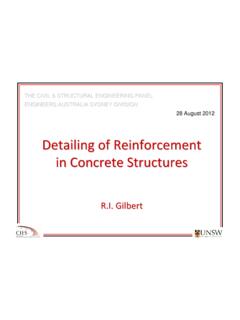
10 Actual carriage spacing is the carriage width plus 3/4 for the Tabulated track load is the full weight of carriage, shelving, decking, track, and media divided by the actual carriage Actual design track load can be calculated by using the ratio of the tributary track width divided by the standard track spacing times the track load (or wheel load).TAB Products Co. uses four standard track spacing; 4 ft. 2 in., 5 ft. - 2 in., 6 ft. - 2 in., and 7 ft. - 2 in. Custom spacing is available at a small increase in cost. The track load can be obtained using tributary carriage length for each track. See Figure 3. Compute tributary carriage length and then calculate the track load from the Track Loading Chart. The maximum wheel load may be calculated in a similar manner. Tributary Carriage Length (example)Figure 3 After the track line loads are calculated from the Track Loading Chart, the Floor slab can be reviewed for strength and deflection.