Transcription of FLOW OF GASES THROUGH TUBES AND ORIFICES
1 2 FLOW OF GASES THROUGH TUBES AND ORIFICES R. Gordon Livesey The nature of gas flow in pipes and ducts changes with the gas pressure and its description is generally divided into three parts or regimes. The flow dynamics are characterized by A, the molecular mean free path, in relation to some characteristic dimension such as the diameter of a pipe. The flow regime cannot be determined from the mean free path alone but only from the relation of this parameter to the characteristic dimension. The relation is known as the Knudsen number, defined as* 1 Kn=d' Three regimes are generally identified: ( ) 1. Free Molecular Flow. The mean free path is of the same order as, or greater than, the characteristic dimension (the range of relatively large Knudsen numbers)~ and gas dynamics are dominated by molecular collisions with the walls of the retaining vessel or pipe.
2 2. Continuum Flow. The mean free path is small compared with the characteristic dimension (the range of small Knudsen numbers), and intermolecular collisions are much more frequent than wall collisions. In this regime the properties of the gas * In the literature the Knudsen number may be variously defined, for a cylindrical tube. as AId, dj)." AIR, or RjA. Foundations of vacuum Science and Technology, Edited by James M. Lafferty. ISBN 0-471-17593-5 1998 John Wiley & Sons, Inc. 81 82 FLOW OF GASES THROUGH TUBES AND ORIFICES (temperature, density, flow velocity) do not vary significantly over several mean free paths and the gas can be considered a continuous medium. The gas dynamics are therefore described and analysed hydrodynamically. Flow in this regime is often referred to as viscous flow, although there are circumstances (such as flow THROUGH short ducts) in which viscosity plays no part.
3 3. Transitional Flow. The transition between continuum and free molecular flow occurs at intermediate values of the Knudsen number where both wall collisions and intermolecular col1isions are influential in determining the flow characteristics. Expressed in terms of pressure and characteristic dimension the Knudsen number is For air at 20oe, with d in mm and Pin mbar we obtain K _ n-Pd . ( ) ( ) Table shows generally accepted range of Knudsen numbers for the three regimes. There is no sharp transition between the regimes, and somewhat different values may be quoted by different authors. The gas factor Fg in the table, used to correct for different GASES , is the ratio of the mean free path for air to that of the gas under consideration (at the same pressure and temperature) and can be calculated from F -A", _ ~a', JM.
4 G--.. 1'/ gas M air ( ) Values of the gas factor for a number of common GASES are shown in Table Applications of vacuum technology range from the lowest pressures attainable 10-14 mbar) THROUGH to around atmospheric pressure, so that all of the regimes described are of interest to workers in this field. One of the main aims of this chapter is to enable calculation of flow under as wide a range of conditions as possible, so that a large number of flow equations is presented. The widespread availability of scientific calculators) personal computers, and mathematical software means that some of the more cumbersome formulae are considerably less daunting than in times past. However, the "back of an envelope" is stm a much favored tool of scientists and engineers and rough calculations are often sufficient, so that approximations will be given wherever possible.
5 Equations for the molecular, continuum and transitional Table Flow Regimes versus Knudsen Number and Pressure Regime Molecular Transitional Continuum Kn (A/d) Kn > > Kn > Kn < P (mbar), d (mm) PdFg < < PdF 9 < PdFg > FLOW CONDUCTANCE, IMPEDANCE, AND GAS THROUGHPUT 83 Table Properties of Some Common GASES at 20 C Relative Molecular Viscosity Viscosity Ratio Gas Mass Pa' s x 10-6 (Air/Gas) ~ H2 2 He 4 H20 (vapor) 18 N2 28 Air 29 1 1 O2 32 Ar 40 CO2 44 regimes are discussed in Sections , , and , respectively. For the most part, derivations are not given since there are textbooks and papers where the basic theories a~e discussed extensively; several references are listed in each section for the reader interested in studying the subject in more detail. All equations are written at least once in the text in SI units; where numerical coefficients are given~ the units used are stated.
6 Except for the discussion of adiabatic compressible flow, it is generally assumed throughout this chapter that isothermal conditions apply. FLOW CONDUCTANCE, IMPEDANCE, AND GAS THROUGHPUT In the field of vacuum science and technology it is common practice to express gas flow rate as throughput in pressure-volume units. The symbol Q is normally used and the throughput of gas at a particular pressure is then If the volumetric flow rate is due to a pump dV A=p_ =PS \t dt ' where S is the speed (or volumetric rate) of the pump at the pressure P. ( ) ( ) The pumping speed available at a chamber will be affected by restriction due to connecting pipework. One of the most common problems in vacuum technology is to estimate the loss in speed due to such restrictions (system design is covered in Chapter 9).. Knudsen [1] first introduced the notion of a pipe as an impedance or resistance in the electrical sense and Dushman [2] introduced the concept of conductance) which is defined by the relation ( ) 84 FLOW OF GASES THROUGH TUBES AND ORIFICES where Pf,I is the upstream pressure and Pd is the downstream pressure.
7 These pressures normally refer to values in (perhaps notional) plenums at the entrance and exit of a duct or a system fitting such as a valve. Gas flow conductance is thus analogous to electrical conductance, with pressure difference being the analogue of voltage differ-ence and Q the analogue of current. The reciprocal of conductance (resistance or impedance, Z = 1/C) could equally wel1 be used; however, conductance has come into common usage in vacuum technology mainly because of its intuitive relation to volume flow rate and pumping speed. Applying this concept to a set of pipes or components in series, the net conductance is found from ( ) The net speed of a pump in series with a component or pipe is found in a similar way: ( ) In practice it is seldom quite so easy as these equations imply. Some care is needed with combinations of components, and this is discussed in Section in relation to molecular flow.
8 In continuum flow, conductance depends in a complicated way on the flow conditions, and a better approach is to calculate the pressure ratio (Kp) across a component or series of components. It is usually assumed that continuity applies THROUGH a system; that is, the THROUGH -put is the same THROUGH all sections. This will be the case as long as sufficient time has elapsed (from opening a valve or starting a pump for example) and there are no temperature differences between the points of interest. In many common situations, steady conditions are a reasonable assumption. (Some cases of unsteady molecular flow are covered in Section ) If Pd is the inlet pressure to a pump of speed S which is connected via a pipeline or component to a chamber, then, assuming steady conditions, the speed (SIl) and pressure (Pf,I) at the chamber are simply related by so that S K' p ( ) ( ) In this way, the net pumping speed can be found if the pressure ratio can be calculated.
9 From the definition of conductance ( ) Dividing THROUGH by the downstream pressure JPd and rearranging gives ( ) MOLECULAR FLOW 85 This calculation is often easier than taking the reciprocal of a sum of reciprocals, and Kp is the factor by which the pumping speed is reduced. MOLECULAR FLOW One of the fundamental assumptions in the derivations of molecular flow conductance is that molecules scatter from a surface according to a cosine distribution. This is also referred to as diffuse or random scattering and means that there are no favored directions. A scattered molecule has the same probability of emerging in any direction, and this is unrelated to its direction of incidence. There are special circumstances in which nondiffuse scattering may occur, but for microscopically rough surfaces the diffuse scattering law is well established theoretically and experimentally [3-5].
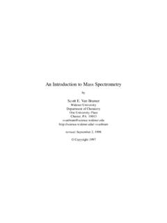
10 Figure shows the distribution of molecules emerging from an aperture and from TUBES of various lengths. The lengths of the vectors are proportional to the number of molecules emerging in that direction. It is noticeable that the longer the tube, the more heavily weighted is the emerging flux to the tube axis. This is an indication of what occurs inside a tube. An observer close to the entrance (looking upstream) will see the entrance plane as a diffuse source. Deep inside the tube an observer will see a pertur-bed flux which is peaked toward the axis. This is often referred to as the beaming effect of a tube. The aperture in Fig. acts as a plane cosine emitter, and the molecular flux shows a spherical distribution. At small angles to the plane the flux of molecules is reduced, Fig. Angular distribution of molecules exiting TUBES of various length-to-diameter ratios.