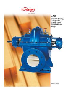
Transcription of Flowserve Pump Division - Consolidated Pumps Ltd
1 Flowserve Pump Division Installation, Operation and Maintenance IDP Pumps Models CPX, cpxr & cpxn . FRAME MOUNTED. CHEMICAL PROCESS Pumps . Instruction manual C937KH013 - 03/02. (incorporating C937KH054). INSTRUCTION manual CPX, cpxr & cpxn ENGLISH C937KH013 - 03/02. INTRODUCTION. Flowserve Flowserve 's products and brands are the leading names in their fields: the CPX range of process Pumps specifically focus on demanding chemical process applications. The Pumps are manufactured at modern facilities, utilising state of art equipment and sophisticated quality control techniques. Flowserve is proud of earning preferred supplier status to many of world's leading processing companies. Engineered, manufactured, sold and serviced to ISO 9001 quality certification, Flowserve Pumps are truly world class products. With more than 120 years of experience in servicing the needs of world-wide process industries, Flowserve has become the unchallenged leader in hydraulic design engineering, materials expertise and application know-how.
2 Committed to continuous quality improvement, Flowserve controls the complete product life cycle - from application engineering, design, melting and casting, to cellular manufacturing, to assembly and testing, to the supply of aftermarket products, repair and diagnostic services. Flowserve is on hand to provide technical support and special services specific to the needs of its customers. Copyright All rights reserved. No part of this manual may be reproduced, stored in a retrieval system or transmitted in any form or by any means without prior permission of Flowserve Pump Division . CE Mark System It is a legal requirement that machinery and equipment put into service within the European Union shall conform with the applicable European Union Directives covering Machinery, Low Voltage Equipment and EMC. Where applicable the European Union Directives cover important Safety aspects relating to machinery and equipment and the satisfactory provision of technical documents and safety instructions.
3 This document incorporates information relevant to these Directives. The manual should be read prior to installing, operating, using and maintaining the equipment. The equipment must not be put into service until all the conditions relating to safety noted in the manual have been met. Disclaimer Flowserve manufactures products to exacting International Quality Management System Standards (ISO 9001) as certified and audited by Lloyd's Register Quality Assurance Limited. Genuine parts and accessories have been designed, tested and incorporated into the products to ensure their continued product quality and performance in use. As Flowserve cannot test parts and accessories sourced from other vendors the incorrect incorporation of such parts and accessories may adversely affect the performance and safety features of the products. The failure to properly select, install or use authorised Flowserve parts and accessories is considered to be misuse.
4 Damage or failure caused by misuse is not covered by Flowserve 's warranty. In addition, any modification of Flowserve products or removal of original components may impair the safety of these products in their use. 2.. INSTRUCTION manual CPX, cpxr & cpxn ENGLISH C937KH013 - 03/02. 1 NAMEPLATE & WARNING LABELS. Nameplate For details of nameplate, see the Declaration of conformity. Warning labels Oil lubricated units only 3.. INSTRUCTION manual CPX, cpxr & cpxn ENGLISH C937KH013 - 03/02. 3 DO NOT RUN THE PUMP AT. 2 SAFETY. Duty conditions ABNORMALLY HIGH OR LOW FLOW RATES. Operating at a flow rate higher than normal or at a flow This pump has been selected to meet the duty rate with no back pressure on the pump may overload and service conditions advised on your order. The the motor and cause cavitation. Low flow rates may acknowledgement of these conditions has been sent cause a reduction in pump/bearing life, overheating of separately to the Purchaser.
5 A copy should be kept the pump, instability and cavitation/vibration. with this manual . 1 NEVER DO MAINTENANCE WORK. If there is any doubt as to the suitability of the WHILST THE UNIT IS CONNECTED TO POWER. pump for the application intended, contact Flowserve for advice, quoting the pump serial number. 2 NEVER APPLY HEAT TO. REMOVE IMPELLER. Safety action Trapped lubricant or vapour could cause an explosion. Always co-ordinate repair activity with operations personnel, and follow all plant safety requirements and 2 HANDLING COMPONENTS. applicable safety and health laws/regulations. Many precision parts have sharp corners and the wearing of appropriate safety gloves and equipment is required THIS IS A SUMMARY OF CONDITIONS AND when handling these components. To lift heavy pieces ACTIONS TO PREVENT INJURY TO PERSONNEL above 30kg (66lbs) use a crane corresponding to the AND DAMAGE TO EQUIPMENT.
6 Mass and in accordance with current local regulations. 2 This sign indicates safety instructions 2 DRAIN PUMP AND ISOLATE. where non-compliance would affect personal safety. PIPEWORK BEFORE DISMANTLING THE PUMP. 1. The appropriate safety precautions should be taken This symbol indicates electrical safety where the pumped liquids are hazardous. instructions where non-compliance would affect personal safety. 2 FLUORO-ELASTOMERS. 3. (When fitted to high temperature units). This symbol indicates safety instructions where When a pump has experienced temperatures over non-compliance would affect the safe operation or 250 C(482 F), partial decomposition of fluoro- protection of the pump or pump unit. elastomers (eg viton) will occur. In this condition these 3 PREVENT EXCESSIVE EXTERNAL. are extremely dangerous and skin contact must be avoided. PIPE LOAD. Do not use pump as a support for piping.
7 Do not 2 THERMAL SHOCK. mount expansion joints so that their force, due to Rapid changes in the temperature of the liquid within internal pressure, acts on the pump flange. the pump can cause thermal shock, which can result in 3 ONLY CHECK DIRECTION OF MOTOR. damage or breakage of components. Thermal shock should be avoided, particularly so where the material ROTATION WITH COUPLING ELEMENT/PINS of the pump is not resistant to such loading. REMOVED. Starting in reverse direction of rotation will damage the 2 HOT (and cold) PARTS. pump. If hot or freezing components or auxiliary heating 3 START THE PUMP WITH OUTLET. supplies can present a danger to operators, they must be shielded to avoid accidental contact. If complete VALVE CLOSED protection is not possible, machine access must be This is recommended to avoid the risk of overloading limited to maintenance staff only.
8 Note: drive motors and damaging the pump motor at full flow. Pumps and bearings may be hot. may be started with the valve open only on installations where this situation cannot occur. IF THE TEMPERATURE IS GREATER THAN 80 C. 3 ENSURE CORRECT LUBRICATION. (175 F) OR BELOW 5 C (20 F), A VISUAL. WARNING INDICATOR SUCH AS A WARNING. (See: Making ready for operation - Lubrication.) PLATE MUST BE PLACED CLEARLY ON THE. 3 NEVER RUN THE PUMP DRY. EQUIPMENT. 2 HAZARDOUS LIQUIDS. 3 INLET VALVES TO BE FULLY OPEN When the pump is handling hazardous liquids care WHEN PUMP IS RUNNING must be taken to avoid liquid contact using the Running the pump at zero flow or below the appropriate health and safety procedures. Pump recommended minimum flow continuously will cause location and personnel access/training should consider the shaft, packing or mechanical seal to run hot and and address these site dangers.
9 Fail within a short time. 4.. INSTRUCTION manual CPX, cpxr & cpxn ENGLISH C937KH013 - 03/02. Potentially explosive atmospheres Always check that the driver, drive coupling assembly and pump equipment are suitably rated and/or certified for the classification of the specific atmosphere in which they are to be installed. See section 17, Certification. 5.. INSTRUCTION manual CPX, cpxr & cpxn ENGLISH C937KH013 - 03/02. 3 CONTENTS. PAGE PAGE. INTRODUCTION 2 11 STOPPING AND SHUTDOWN 13. 1 NAMEPLATE & WARNING LABELS 3 12 PREVENTATIVE MAINTENANCE AND. SERVICING. 2 SAFETY Maintenance schedule 14. Duty conditions 4 Routine inspection (daily/weekly) 14. Safety action 4 Periodic inspection (6 monthly) 14. Potentially explosive atmospheres 5 Lubrication data 14. Gland packing 14. 3 CONTENTS 6 Mechanical seals 14. Setting CPX & cpxn impeller 4 PUMP TECHNICAL DATA front clearance 14.
10 Performance 7 Setting cpxr impeller clearance 15. Noise level 7. Pressure limits 7 13 DISMANTLING AND ASSEMBLY. Recommended screw torques 7 Dismantling 15. Flange loads 7 Examination of parts 16. Pump lubricants 8 Assembly 16. 5 PRODUCT DESCRIPTION 14 SEALING ARRANGEMENTS. General 9 Single seal types 18. Pump casing 9 Cartridge seal types 19. Impeller 9 Tandem seal types 19. Shaft 9 Double seal types 20. Bearing housing 9 External seal types 20. Pump bearings and lubrication 9 Packed gland seal types 20. Seal housing 9. Shaft seal 9 15 SPARE PARTS. Driver 9 Ordering of spares 21. Accessories 9 Storage of spares 21. Recommended spares 21. 6 STORAGE 9. 16 GENERAL ARRANGEMENT DRAWING 21. 7 INSTALLATION. Unpacking and inspection 9 17 CERTIFICATION 21. Handling 9. Location 10 18 SUPPLEMENTARY INSTRUCTION. Foundation 10 MANUALS 21. Grouting 10. Alignment of couplings 10 19 CHANGE NOTES 21.


