Transcription of Flux-canceling electrodynamic maglev suspension: part II ...
1 1964 IEEE TRANSACTIONS ON MAGNETICS, VOL. 35, NO. 3, MAY 1999 Flux-canceling electrodynamic MaglevSuspension: Part II Test Results and Scaling LawsMarc T. Thompson,Member, IEEE, and Richard D. Thornton,Life Fellow, IEEEA bstract electrodynamic suspensions (EDS) are highly un-damped and require some form of active control or a secondarysuspension to achieve adequate ride quality. This paper reportson efforts to develop a version of EDS that uses controllable mag-netic forces to eliminate the need for any secondary magnetic forces act directly on the guideway and avoid theneed to have unsprung weight and a secondary suspension . Itis shown that the energy required to effect this control can beless than 1% of the energy stored in the suspension magnets,so a modest size controller can be used. The same controllercan also provide lift at very low speeds and thereby eliminatethe need for a separate low-speed suspension system.
2 A set ofscaling laws is described which is used to size a full-scale high-temperature superconductor (HTSC)-based suspension test fixture was also used to verify the use of zero velocity lift, where ac excitation is used in the suspension coils to achievelift at low train Terms Control systems, high-temperature supercon-ductors, inductance, levitation, magnetic analysis, magneticforces, magnetic levitation, maglev , modeling, superconductingcoils, superconducting INTRODUCTIONTHE design and analysis of a new iron-core Flux-canceling magnetic suspension suitable for high-temperature superconductors (HTSC) is described. A 1/5-scalemodel of this suspension has been designed and tested witha high-speed rotating wheel test facility. A new low-costmultiple-loop guideway has been tested and lift, drag, andguidance forces have been measured at operating speedsapproaching that of a full-scale train.
3 These results arecompared to predictions based on simple circuit models, withgood vertical control system has been designed and testedto improve ride quality through differential control of themagnet currents. The test fixture has also been used to validatethe concept of lift generation at zero train velocity by acexcitation of the main magnet coils. Scaling laws have beenapplied to the results and predictions made for a full-scaleHTSC suspension operating at 40K. Further work in this areaManuscript received June 3, 1998; revised January 11, T. Thompson was with the Laboratory for Electromagnetic and Elec-tronic Systems, Massachusetts Institute of Technology, Cambridge, MA 02139 USA. He is now at 25 Commonwealth Road, Watertown, MA, 02472 USA (e-mail: and with Worcester Polytechnic Institute, Worcester,MA 01609 D. Thornton was with the Department of Electrical Engineering andComputer Science, Massachusetts Institute of Technology, Cambridge, MA02139 USA.)
4 He is now with Magnemotion, Inc., Sudbury, MA 02776 USA(e-mail: Item Identifier S 0018-9464(99) help overcome one of the fundamental limitations ofelectrodynamic (EDS) magnetic levitation ( maglev ) the factthat there is zero levitation force at zero train velocity and alow speed suspension is BASICMAGLEVMEASUREMENTSA. maglev Test ProgramDetails of the test fixture including speed control of thetest wheel and operation of the data acquisition systemare discussed in [1] [4] and a companion paper in theseTRANSACTIONS. The goals of the test program were as follows. Measure forces and moments for the magnets in differentequilibrium positions and for different linear velocitiesusing a multi-axis force sensor. Use the resultant data toverify models. Test the viability of using ac excitation of the magnet coilsto achieve significant lift force at zero train velocity. Test the viability of actively controlled high temperaturesuperconducting magnets in a magnetic secondary sus-pension by testing the magnet with a low-friction airbearing which allows vertical motion of the Basic Measurements Using Force SensorThe result of several test wheel runs is shown in Fig.)
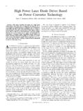
5 1where the test wheel speed was varied from 0 600 RPM (linearspeed, 0 50 m/s). In Fig. 1(a), the magnet was set below thenull position, and a positive lift force is measured. In Fig. 1(b),the magnet was cm above the null position and anegative lift force is measured. The drag force shows a peak atapproximately 20 25 m/s. Also of note is the guidance force,which is a significant fraction of the lift force. In Fig. 1(c), themagnet was set near the null position, and the lift and dragforces are minimized important results from this test are that the dragpeak velocity is approximately 20 25 m per second, whichis significantly lower than the maximum test wheel , data has been taken at speeds significantly higherthan the drag peak velocity. This critical velocity will decreasesignificantly for a full-scale maglev magnet, shown withscaling laws developed later in this paper. Also, the guidanceforce for this configuration is a significant fraction of the liftforce.
6 This may enable a design without additional 9464/99$ 1999 IEEETHOMPSON AND THORNTON: Flux-canceling electrodynamic maglev suspension : PART II1965(a)(b)Fig. 1. Lift, drag, and guidance force per coil,NI=2750 A turns per coil, all eight coils energized. (a) Magnet below nullposition atz= 0:4cm. (b) Magnet above null position atz=1 result of calculation based on the electrodynamic mod-els described previously is shown in Fig. 2 and compared tomeasured data taken with the test wheel in the range 0 600 RPM (0 50 m/s). There is good agreement for the 15-coilmodel for the lift forceand the drag forceThe simplecircuit model predicts a drag peak velocity of approximately15 m/s, while the measured drag peak is approximately 20 25m/s. The accuracy of the drag force can be further improvedby accounting for parasitic eddy currents in the guideway rim,effects that are not considered by the circuit TRANSACTIONS ON MAGNETICS, VOL.
7 35, NO. 3, MAY 1999(c)Fig. 1.(Continued).Lift, drag, and guidance force per coil,NI=2750 A turns per coil, all eight coils energized. (c) Magnetslightly above null position atz=0 to Fig. 2, the excitation vector (top left) is approx-imately a half sinusoid, corresponding to the applied magneticfield integrated over the area of the guideway loops. The shapeof this excitation vector insures that only the first and secondnatural modes will be excited. Measurements on drag force(bottom right) bear this out, as the measured drag peak velocitywas approximately 25 m/s and the electrodynamic modelpredicts40 m/s. Higher-order modes are at significantlyhigher natural lift force model shows good agreement with experimentin the 0 50 m/s range, although there is divergence at highervelocities. This may be due to the effects of higher-ordermodes at higher frequencies, but further study is THEPROBLEM OFRIDEQUALITYCONTROLThe problem of stability has long been recognized asone of the fundamental design challenges for the successfulcommercialization of electrodynamic maglev .
8 The stability ofmaglev vehicles is of considerable interest due to its effects onpassenger safety and structural requirements. Many theoreticaland several experimental studies have been done to illustratethis al.[5] considered the stability of a levitatedsuperconducting current ring and evaluated passive dampingtechniques as well as active stabilization. Davis and Wilkie[6], Fink and Hobrecht [7], and Reitz and Davis [8] studied theproblem of infinitely-long wires traveling over an infinite con-ducting sheet and found vertical and transitional instabilitiesin the absence of air problem of negative magnetic damping was studied byYamada, Iwamotoet al., [9], [10] who built an experimentalfacility in 1973. A ferrite magnet was suspended and allowedto vibrate near a rotating aluminum drum. The dampingbehavior of the system was observed at various operatingspeeds, and it was found that negative damping exists forlinear velocities above a critical velocity.
9 For a full-scale traintraveling over a sheet guideway, these results extrapolated tonegative damping for train speeds higher than60 [11] and later Iwamotoet al.[10] applied theimpedance-modeling method to predict lift and drag forcesand to study the static and dynamic stability of variousvehicle-guideway configurations. Iwamoto predicts a negativedamping coefficient for train speeds over50 m/s travelingover a trace with discrete loops. Iwamoto recommends usingpassive damping to achieve good ride conclusion of many of these early studies was thatsome form of damping is needed for acceptable ride quality,even in the presence of aerodynamic drag. Passive dampingdevices were considered, but the use of conducting plates ortuned coils between the lift magnets and the sheet guidewaydid not provide sufficient damping for the expected guidewayroughness. It was concluded that some sort of secondarysuspension or active control is MIT team of Kolm, Thornton, Brown and Iwasa[12] studied the stability of the EDS magneplane systemTHOMPSON AND THORNTON: Flux-canceling electrodynamic maglev suspension : PART II1967 Fig.
10 2. Predictions of electrodynamic model with magnet+ cm above null position. Upper left, coil excitation vectorfvg;upper right, inducedloop currentsfIgat 100 and 200 Hz. Lower left, comparison of measured to calculated lift force versus velocity; lower right, comparison of measuredand calculated drag force versus a 1/25th-scale model and found the suspension to beunderdamped and prone to catastrophic accelerations. Oneimportant development for vertical control was the use of thelinear synchronous motor for heave stability studies have focused on dynamic insta-bilities and the effects of mode coupling. Chu and Moon[13], demonstrated instabilities in a two degrees-of-freedom( ) electrodynamic maglev model, showing limit cycleoscillations at operating speeds near the maglev drag peak. Dueto the small scale of their model, aerodynamics significantlyaffected their results.