Transcription of Foamproport Bladder Tank - HD Fire Protect
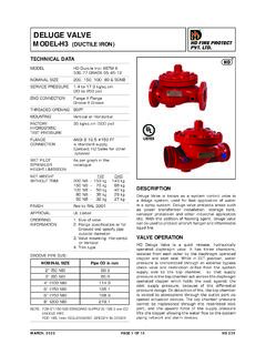
1 MARCH, 2021HD 191 PAGE 1 OF 12HD FIRE PROTECTPVT. LTD. Bladder TANK PROPORTIONING SYSTEM PRE-PIPEDTANK MOUNTING Vertical or Horizontal TYPECONCENTRATE For Vertical Tank 140 liters STORAGE CAPACITY to 7500 liters (36 TO 2000 gallon (US)) For Horizontal Tank 140 liters to 15000 liters (36 to 4000 gallon (US))MAXIMUM WORKING 12 Bar (175 PSI) PRESSURE FACTORY HYDRO As per ASME code TEST PRESSUREFLOW Refer Ratio Controller Product Data Sheet-HD 263 VESSEL Carbon Steel as per ASME CONSTRUCTION Code Section VIII Div 1, for unfired pressure vesselsCE Mark OptionalASME U STAMP OptionalBLADDER Buna-NEXTERNAL PIPING Water side: Carbon Steel Seamless Pipe Foam Concentrate side: Stainless Steel Wafer type with Stainless CONTROLLER Steel 304/CF8 standard supply Optional: Stainless Steel 316/CF8M or Bronze Optional - Flanged TypeVENT AND DRAIN Ball valveAPPROVALS UL-Listed or FM ApprovedOPTIONAL SUPPLY Refer to page 3 FINISH Red RAL 3001 ORDERING Specify: INFORMATION 1) Tank type, vertical or horizontal 2) Storage capacity 3) Model number, size of ratio controller with flow and pressure 4) Type of foam concentrate to be used and percentage of induction required 5) Optional items 6) UL or FM Approval RequirementTECHNICAL DATAAPPLICATIONThe Bladder Tank Foam Proportioning System utilises water pressure to inject foam concentrate into water supply and automatically proportions foam concentrate over wide range of flow and pressure, with very low pressure drop.
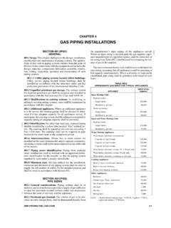
2 This system does not require a foam concentrate supply Bladder Tank Foam Proportioning Systems are available with vertical and horizontal Bladder tanks . The carbon steel tanks are designed and constructed in accordance with ASME Code Section Vlll for unfired pressure vessels. The maximum working pressure is 12 Bar (175 PSI). The vertical tank assembly is supported by legs welded to tank with provision for anchoring. The horizontal tanks are supported by two saddles welded to the tank and drilled for anchoring. Tank is provided with lifting system is supplied with pressure vessel, Bladder , fill and drain valve for water and foam concentrate, ratio controller and vent valve. Note: The above images are for representative purpose, actual product may vary depending on the required accessories & , 2021HD 191 PAGE 2 OF 12HD FIRE PROTECTPVT. and sight gauge assembly are supplied as optional items on request.
3 All valves are labeled showing normal working position and function. All tanks are oversized for allowing thermal expansion of the foam concentrate, if OF OPERATIONThe instructions for filling are provided with the equipment. Once the main water flow is established and water inlet and foam outlet valves are opened, the water enters the area between vessel wall and Bladder , applying pressure to the Bladder . The foam concentrate is forced out of the Bladder through the foam concentrate outlet pipe and into the ratio controller through metering orifice. The concentrate pressure and water inlet pressure at ratio controller will be same, as the main water supply pressure is utilised to expel the foam from the Bladder . The water flowing through the ratio controller jet creates a low pressure area for foam concentrate. This injects the concentrate in to the ratio controller through an accurate sized orifice proportioned to water venturi.
4 This ensures correct proportioning over a wide range of flow Bladder tank proportioning system operates on same principle as that of a balance pressure proportioning system. In Bladder system, the Bladder is used as diaphragm to separate the water and foam concentrate within the tank. The foam concentrate is injected into the ratio controller utilising water system is also supplied with foam concentrate control valve as an optional item. The valve allows concentrate flow only when minimum of water pressure is established in the system. For pressure drop and flow characteristics refer catalogue of ratio FIRE Bladder tanks and proportioners are UL Listed and FM Approved with various HD foam concentrates, refer individual listing and approval data. U stamp (The American Society of Mechanical Engineers- ASME) code stamp. This ASME certification is optional.
5 Bladder tanks 900 Liters and larger are CE marked on conformance with the European Pressure Equipment Directives. CE marking is OF HORIZONTAL/ VERTICAL Bladder TANKSA dvantages of Horizontal Bladder tanks (i) Better stability than vertical tank in earthquake prone area(ii) Easier to refill than vertical tanks (iii) Easy to transport, store and install(iv) Large CapacityAdvantages of Vertical Bladder tanks (i) Require less floor space than horizontal tanksINSTALLATION, INSPECTION AND MAINTENANCEAn installation, inspection and maintenance manual is packed with each unit. The manual provides detail schematic, initial procedure, inspection and maintenance procedures. The instruction manual must be read carefully and followed during installation and commissioning of the few initial successful tests an authorised person must be trained to perform inspection and testing of the system.
6 It is recommended to carry out physical inspection of the system regularly, the inspector should verify that no damages have taken place to any component and all the valves are in their proper position as per the system requirement. The system should be fully tested at least once in a year and in accordance with applicable NFPA code or in accordance to the guidelines of the organisation having local not turn off the system or any valve to repair or test the system, without placing a roving Fire Patrol in the area covered by the system. The patrol should continue until the system is put back in service. Also inform the local security personnel and the control room so that a false alarm is not ) Do not weld on the tank as it may damage the Bladder fitted inside the ) Release pressure before an inspection and maintenance of the ) Sight gauge is not pressure tight, so before taking concentrate level reading, tank pressure must be ) The Bladder tank is to be installed under a shed to avoid direct sunlight on the ) While designing a foam system, step shall be taken to allow for removal of the internal centre tube(s).
7 The centre tubes are full length and/or height of the Bladder ) ASME Code may require over pressure protection before pressurising the system. HD FIRE does not supply an over pressure relief valve with the tanks . It shall be the owner s responsibility to provide over pressure protection for the tank in accordance to ASME ) Foam concentrate filling procedure must be followed. Incorrect filling procedure may damage the Bladder . HD product have limited warranty and incorrect fill procedure will void the , 2021HD 191 PAGE 3 OF 12HD FIRE PROTECTPVT. ) The foam concentrate is to be filled in the Bladder very carefully to avoid rupture of Bladder . The filling guidelines provided with the equipment must be strictly ) Air supply with regulator (0 to kg/sqcm) required during filling procedure, to be arranged by installer / ) Water supply at kg/sqcm required for tank filling during commissioning, to be arranged by installer / ) Concentrate fill pump need to be arranged by installer / ) A minimum length of 5 (five) times the pipe diameter of unobstructed straight pipeline should be provided at the inlet and outlet of the ratio controller, where pipe diameter is the nominal size of the ratio ) FM Approval of Bladder tank is applicable only if FM Approved Bladder tank, Ratio Controller, Foam Concentrate and Discharge Devices are )
8 Foam Concentrate Control Valve is requirement for FM Approval and is not permited by UL. Hence tanks will be either UL Listed or FM ) Multiple Ratio Controllers cannot be used if it is UL Listed Bladder ) FM Approved Bladder tank permits maximum two Ratio ) Each tank is designed & tested for specific type of foam concentrate, hence specify in order the concentrate type to be used. OPTIONAL SUPPLY Sight gauge with shut off and drain valve (glass or polycarbonate material) Ladder Pressure Gauges Concentrate control valve Filling kit with foam concentrate filling pump Stainless steel pipe for water supply side Stainless steel pipe & valve standard supply SS304/CF8. Optional is SS316/CF8M or SS316L/CF3M Painting as per specific requirement Seismic designed tanks Custom design for higher rating, material and dimension Internal surface is epoxy painted as standard supply, or any other paint as per customer requirement Ratio controller material Bronze, Stainless steel CF8M Relief valve is not included in standard supply it is optional as per specific customer requirement Corrosion VALVE (OPTIONAL SUPPLY)(i) Thermal Relief valve(ii) Full flow, as per ASME(iii) Full flow, ASME U StampedLISTING & APPROVAL1) Bladder tank proportioning system is UL Listed or FM Approved as pre-piped ) Listing and Approval is valid only when used in the manner as outlined in the applicable Listing and ) Foam Concentrate Control Valve is standard supply with FM Approved Bladder ) CE marking is )
9 ASME U stamp is DETAILSi) All the tank openings will be plugged for ) All pre-piped pipes, valves, pressure gauges, sight gauge etc will be packed separately for ) Tank will be mounted on pallet with crate all over as standard packing system of HD FIRE. For any custom packing requirement contact HD , 2021HD 191 PAGE 4 OF 12HD FIRE PROTECTPVT. Bladder TANK WITH SINGLE RATIO CONTROLLERSIGHT GLASSSIDE VIEWELEVATIONELECTRICAL CONNECTION DIAGRAMVALVE OPEN YELLOW CAMBOTTOM SWITCHTOP VIEW LIMIT SWITCH BOXWITH COVER OPENNONCCOMCOMNONCVALVE CLOSED RED CAMTOP SWITCHNONCCOMCOMNONCV5V4 SIGHT GLASSV6V8V7V3V9 TANKBLADDEROUTLETSOLUTIONFOAMF2F1B1B2 INLETWATERV2V1 RCWFOAM CONCENTRATE LINEWATER LINEVERTICAL- AUTO. VALVE WITH LIMIT SWITCHES- NON RETURN VALVE- BALL VALVE- VALVE- THERMAL RELIEF VALVE- RATIO CONTROLLER - PRESSURE GAUGESYMBOLS & PRESSURE SHUT OFF VALVETANK DRAIN VALVETANK VENT VALVEBLADDER VENT VALVEBLADDER FILL / DRAIN VALVESIGHT GLASS FILL VALVESIGHT GLASS DRAIN VALVEMANUAL OVER RIDE VALVERESETTING VALVEAUTO.
10 FOAM CONCENTRATE VALVE WITH LIMIT SWITCHNORMAL POSITIONMANUAL SYSTEMAUTO. SYSTEM---OPENOPENCLOSEDCLOSEDCLOSEDCLOSE DCLOSEDCLOSEDCLOSEDCLOSEDCLOSEDCLOSEDCLO SEDCLOSED---OPEN---CLOSEDCLOSEDSCHEMATIC DIAGRAMP. & I. DIAGRAMRCRC(ONLY WITH FM APPROVED TANK)V9 THERMAL RELIEF VALVECLOSEDCLOSEDMARCH, 2021HD 191 PAGE 5 OF 12HD FIRE PROTECTPVT. Bladder TANK WITH TWO RATIO CONTROLLERSV5V4 SIGHT GLASSV6V8V7V3V9 TANKBLADDEROUTLETSOLUTIONFOAMF2F1B1B2 INLETWATERV2V1 RCWFOAM CONCENTRATE LINEWATER LINEVERTICALOUTLETSOLUTIONFOAMF2F1B1B2 INLETWATERV2V1 RCWSIGHT GLASSSIDE VIEWELEVATIONELECTRICAL CONNECTION DIAGRAMTOP VIEW LIMIT SWITCH BOXWITH COVER OPENNONCCOMCOMNONCNONCCOMCOMNONC- AUTO. VALVE WITH LIMIT SWITCHES- NON RETURN VALVE- BALL VALVE- VALVE- THERMAL RELIEF VALVE- RATIO CONTROLLER - PRESSURE GAUGESYMBOLS & ABBREVIATIONSCHEMATIC DIAGRAMP. & I. DIAGRAMVALVE OPEN YELLOW CAMBOTTOM SWITCHVALVE CLOSED RED CAMTOP SWITCHRCRCRC(ONLY WITH FM APPROVED TANK) PRESSURE SHUT OFF VALVETANK DRAIN VALVETANK VENT VALVEBLADDER VENT VALVEBLADDER FILL / DRAIN VALVESIGHT GLASS FILL VALVESIGHT GLASS DRAIN VALVEMANUAL OVER RIDE VALVERESETTING VALVEAUTO.