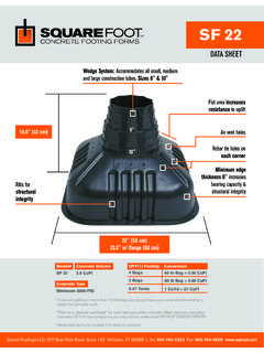
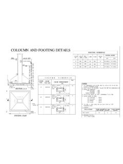
Transcription of Footing Chart** - Wesure Metal Manufacturing
1 Footing Chart** For size andnumber of rebarsee chart above'A''A'6 Minimumcovertypical6 3 1 10 Rebar Line2 Directions - Total 1 Notes:A. Concrete to be a minimum of (20 Mpa), normal portland cement type 10 or type 50 as required, maximum 3/4 (20mm) aggregate, 3 (75MM) All rebar to be tied at intersections. Follow position Footing meets or exceeds National and Alberta Building Code Section Load to be applied in the middle of the pad. Eccentric loading will significantly reduce the capacity of the Wesure Support Systems is not responsible for compliance or application of charts (charts supplied as information only).F. The minimum 254mm Footing thickness is Government (code) The soil bearing load capacities have been adjusted to show the load on the columns alone. The total soil bearing capacity has been reduced by the self weight of the Footing Determine the Footing size according to Load.
2 You must verify soil bearing capacity with engineer PAD REQUIREMENT(S) & SPECIFICATION(S): Allowable Soil Bearing Capacity:2000 (2800 lbs/ft2 factored)2500 lbs/ft2 (3500 lbs/ft2 factored)3000 lbs/ft2 (4200 lbs/ft2 factored) Footing Dimensions(L x W x D)Number & Size of Rebar Maximum Footing CapacityAllowableWorking Loads (Unfactored)Limit State Design (Factored)AllowableWorking Loads (Unfactored)Limit State Design (Factored)AllowableWorking Loads (Unfactored) Limit State Design (Factored)lbskNlbskNlbskNlbskNlbskNlbskN 24 x 24 x 10 4-10M E/W 7, , , , , , x 30 x 10 4-10M E/W 11, , , , , , x 36 x 10 5-10M E/W 16, , , , , , x 42 x 10 6-10M E/W 22, , , , , , x 48 x 10 7-10M E/W 30, , , , , , x 54 x 11 8-10M E/W 37, , , , , , x 60 x 12 10-10M E/W 46, , , , , , x 66 x 12 6-15M E/W 55, , , , , , x 72 x 14 7-15M E/W 65, , , , , , x 78 x 14 8-15M E/W 77, , , , , , x 84 x 16 9-15M E/W 88, , , , , , x 90 x 16 10-15M E/W 101, , , , , , x 96 x 18 12-15M E/W 113, , , , , , x 102 X 18 12-15M E/W 128, , , , , , x 108 x 20 14-15M E/W 141, , , , , , x 114 x 20 15-15M E/W 157, , , , , , ** The Wesure Support Systems suggested Footing design is designed for use with Wesure columns only.
3 It is not compatible with other is a registered trademark ofWestern Sulfur Remelters information is accurate as of the date of publication. Please refer to for the most current October 2010