Transcription of FOR ALL 6-BOLT AND 8-BOLT MOUNT SERIES PTOS
1 FOR ALL 6-BOLT AND 8-BOLT MOUNT SERIES PTOSPTO INSTALLATION AND OPERATOR S MANUALKEEP IN VEHICLEREAD OPERATING INSTRUCTIONSINSIDE BEFORE OPERATING PTOM uncie Power Products, PTO is supplied with a packet containing warning labels. If you did not receive any, or if you need extra, you may order them, no charge, by phone, email, or mail. They are available through your nearest Muncie Power Products distributor or at the number and address below:1-800-FOR-PTOS (367-7867)Muncie Power Products, Inc. Box 548 Muncie, IN This symbol warns of personal injury. Muncie Power Products, Inc.
2 2008 WARNINGREAD MANUAL COMPLETELY INCLUDING THESE WARNINGS ANDOPERATOR S INSTRUCTIONS IN SECTION 3 READ AND UNDERSTAND ENTIRE MANUAL BEFORE INSTALLATION OR OPERATION OF PTO AND DRIVEN EQUIPMENT ALWAYS DISENGAGE THE PTO WHEN THE DRIVEN EQUIPMENT IS NOT IN OPERATION. DO NOT ATTEMPT TO INSTALL OR SERVICE ANY POWER TAKE-OFF WITH THE TRUCK ENGINE RUNNING. PUT THE IGNITION KEYS IN YOUR POCKET BEFORE GETTING UNDER THE TRUCK. DO NOT ALLOW TRUCK ENGINE TO BE STARTED WHILE WORKERS ARE UNDER THE TRUCK. IMMOBILIZE TRUCK WHEELS WITH SUITABLE CHOCKS BEFORE WORKING UNDER TRUCK.
3 BE SURE TO BLOCK ANY RAISED BODY OR MECHANISM BEFORE WORKING ON OR UNDER THE EQUIPMENT. INSTALLED POWER TAKE-OFFS MUST NEVER BE SHIFTED IN OR OUT OF GEAR BY ANY MEANS EXCEPT BY THE CONTROLS IN THE CAB OF THE TRUCK. STAY CLEAR OF SPINNING DRIVESHAFTS TO AVOID BECOMING ENTANGLED AND INJURED. IT SHALL BE THE RESPONSIBILITY OF THE INSTALLER OF A MUNCIE POWER TAKE-OFF TO DECIDE WHETHER TO INSTALL GUARDS IN THE PTO AND/OR DRIVELINE AREA BECAUSE OF POTENTIAL EXPOSURE TO DANGER. THIS IS BECAUSE MOST MUNCIE POWER PTOS ARE INSTALLED BY EQUIPMENT DISTRIBUTORS OR MANUFACTURERS AND THEREFORE, THE RESPONSIBILITY OF THE INSTALLATION IS BEYOND THE CONTROL OF MUNCIE POWER PRODUCTS.
4 OBTAIN PROPER TRAINING BEFORE OPERATING THIS MACHINERY DO NOT INSTALL OR OPERATE EQUIPMENT WHICH HAS NOT BEEN PROPERLY SPECIFIED FOR YOUR EQUIPMENT. ALLOW THE VEHICLE, PTO AND DRIVEN EQUIPMENT TO WARM UP WHEN OPERATING IN WEATHER WHERE TEMPERATURES ARE NEAR OR BELOW FREEZING 32 F (0 C). INSTALL SEPARATE CONTROLS FOR PTO AND DRIVEN EQUIPMENT ALWAYS INSTALL THE SAFETY LABELS PROVIDED AND PLACE THE OPERATOR S MANUAL IN THE VEHICLE GLOVE OF CONTENTSS ection 1 PTO InstallationPTO Installation Instructions .. Plates & Assemblies .. Gear Installation.
5 Blocks .. 2 Activation Kit InstallationActivation Kit Installation Instructions .. Shift Control .. Shift Instructions .. Light Switch Continuity Check .. Equipped with Magnetic Pick-Up Sensor .. SERIES Lectra Shift System .. SERIES Wiring Diagram for E-Hydra-Shift .. SERIES Standard Air Shift System .. SERIES Electric/Air Shift System .. SERIES Double Acting Air Shift System .. SERIES Standard Air Shift System .. Transmission Diagrams .. Shift and SH SERIES Electric/Air Shift System .. Shift and SH SERIES Standard Air Shift System .. Shift Electric/Hydraulic Shift System.
6 Shift Instructions & Tests .. 3 Operator s ManualPower Take-off Warranty .. Shifting Procedure & Precautions .. Shift Operating Notes .. Maintenance .. Light Check .. Torque & Horsepower Ratings .. Troubleshooting Guide .. OPERATOR S MANUALFOR ALL 6-BOLT AND 8-BOLT MOUNT MUNCIE PTOSSECTION 1 PTO INSTALLATIONPTO INSTALLATION INSTRUCTIONSA lways wear safety glasses. Read entire manual before starting installation. 1. There is a packet with the PTO which contains 4 WARNING LABELS. Before adhering the labels, make sure the surfaces are free of dirt and grease.
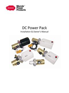
7 Place the labels supplied as follows:There are two (2) labels which measure approximately 4" x 8" which are to be placed on the outside of the vehicle frame rail, making them easy to be seen by anyone who might go under the truck or near the PTO. One label is to be placed on each side of the the body installed on the chassis cover the frame rail, place the label on the body in a position easily visible by anyone who might go under the vehicle or near the PTO. Do not paint over are two (2) 4" X 8" labels supplied and one is to be placed on each side of the may behurt or GETUNDER THISTRUCK IFTHE ENGINEIS RUNNING!
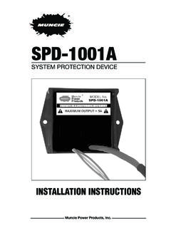
8 NUNCA SEMETA DEBAJODEL CAMI NCUANDA ELMOTOR EST EN MARCHA!Part No. 36M35644 (Rev. 9-06) Muncie Power Products, Inc. 2006 LOCATE ON FRAME 2. The 2" x 3" PTO Equipped Caution Label is to be placed within the cab of the vehicle and in easy view of the vehicle operator. It should be located near the PTO control, when the control is installed in the vehicle dash (See Figure ). This label directs the operator to read the PTO operating instructions on the Visor Label . The Visor Label 4" x 6 " is to be placed on the visor on the operator s side of the vehicle (See Figure ).
9 Do not MOUNT this label on the same side of the visor as the air bag warning label if so equipped. Vehicles with hydraulic dump pumps are supplied with a Warning label to be mounted in clear view of the operator while seated in the driver s seat. Figure VEHICLE ISEQUIPPED WITH APOWER TAKE-OFFREAD AND UNDERSTAND OPERATOR'S MANUAL BEFORE USING THIS TO FOLLOW OPERATING INSTRUCTIONS COULD RESULT IN DEATH OR SERIOUS VEHICULO ESTAEQUIPADO CON UNATOMA DE FUERZAIMPORTANTE. FAVOR DE LEER Y CONSULTAR EL MANUAL DE OPERACION ANTES DE OPERAR Y MANEJAR ESTA UNIDAD. EL NO SEGUIR LAS INSTRUCCIONES DE OPERACION PUEDA RESULTAR EN HERIDAS PERSONALES O EN LA LA CALCOMANIA CERCA DE LOS CONTROLES DE LA TOMA DE FUERZALOCATE VISIBLE AND NEAR PTO CONTROL Muncie Power Products, Inc.
10 2006 Part No. 36M35652 (Rev. 9-06)Part No. 36T38634 Muncie Power Products, Inc. 2006 LOCATE ON VISOR SO IT IS VISIBLE WHEN THE SUN VISOR IS RAISEDUNDERSTAND THIS LABEL BEFORE USING POWER TAKE-OFF (PTO). Refer to Owner's Manual in glove box or on the internet at: TO USE THEPOWER TAKE-OFF (PTO)STATIONARY APPLICATIONS:CHOCK WHEELS BEFOREENGAGING Shift PTOs (including Air Shift)Manual Transmissions1. Push in clutch Shift transmission into Engage Let clutch pedal Shift PTOs (including Air Shift)Automatic Transmissions1. Let engine Apply brakes, while seated in driver's Place shift selector in any drive Engage Shift transmission to neutral or Shift PTOsManual or Automatic Let engine Engage PTO with Resume operating GET UNDER THIS TRUCK IF THE ENGINE IS RUNNING!