Transcription of For M542 V2 - Leadshine
1 User's Manual The content in this manual has been carefully prepared and is believed to be accurate, but no responsibility is assumed for inaccuracies. For Leadshine reserves the right to make changes without further notice to any products herein to m542 improve reliability, function or design. Leadshine does not assume any liability arising out of the application or use of any product or circuit described herein; neither does it convey any license under its patent rights of others. High Performance Microstepping Driver Leadshine 's general policy does not recommend the use of its products in life support or aircraft Version applications wherein a failure or malfunction of the product may directly threaten life or injury.
2 2008 All Rights Reserved According to Leadshine 's terms and conditions of sales, the user of Leadshine 's products in life Attention: Please read this manual carefully before using the driver! support or aircraft applications assumes all risks of such use and indemnifies Leadshine against all damages. 3/F, Block 2, Nanyou Tianan Industrial Park, Nanshan Dist, Shenzhen, China 2008 by Leadshine Technology Company Limited. T: (86)755-26434369 F: (86)755-26402718 All Rights Reserved Web site: E-Mail: Contents Contents Dynamic current setting .. 9. Table of Contents Standstill current 9.
3 1. Introduction, Features and 1 8. Wiring Notes .. 10. Introduction .. 1 9. Typical 10. Features .. 1 10. Sequence Chart of Control Signals .. 11. Applications .. 1 11. Protection 11. 2. Specifications .. 1 Short-voltage and Over-voltage protection .. 11. Electrical Specifications .. 1 Over-current 12. Operating Environment and other 2 Short Circuit 12. Mechanical 2 12. Frequently Asked 12. Elimination of Heat .. 2 Problem Symptoms and Possible Causes .. 13. 3. Pin Assignment and Description .. 3 APPENDIX .. 14. Connector P1 Configurations .. 3 Twelve Month Limited Warranty.
4 14. Selecting Active Pulse Edge or Active Level and Control Signal 3 Exclusions .. 14. Connector P2 Configurations .. 4 Obtaining Warranty Service .. 14. 4. Control Signal Connector (P1) 4 Warranty 14. 5. Connecting the 5 Contact 15. Connections to 4-lead Motors .. 5. Connections to 6-lead Motors .. 5. Half Coil Configurations .. 5. Full Coil 6. Connections to 8-lead Motors .. 6. Series Connections .. 6. Parallel 7. 6. Power Supply Selection .. 7. Regulated or Unregulated Power Supply .. 7. Multiple Drivers .. 8. Selecting Supply 8. 7. Selecting Microstep Resolution and Driver Output Current.
5 8. Microstep Resolution Selection .. 8. Current 9. I II. m542 Microstepping Driver Manual m542 Microstepping Driver Manual Operating Environment and other Specifications 1. Introduction, Features and Applications Cooling Natural Cooling or Forced cooling Introduction Environment Avoid dust, oil fog and corrosive gases The m542 is a high performance microstepping driver based on pure-sinusoidal current Ambient Temperature 0 50 . control technology. Owing to the above technology and the self-adjustment technology (self-adjust 40%RH 90%RH. Operating Environment Humidity current control parameters) according to different motors, the driven motors can run with smaller noise, lower heating, smoother movement and have better performances at higher speed than most Operating Temperature 70 Max of the drivers in the markets.
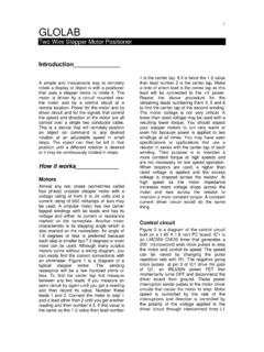
6 It is suitable for driving 2-phase and 4-phase hybrid stepping motors. Vibration Max Features Storage Temperature -20 65 . Weight Approx. 280g (10 oz). l High performance, cost-effective l Automatic idle-current reduction l Supply voltage up to +50 VDC l 15 selectable resolutions in decimal and Mechanical Specifications (unit: mm [inch]). l Output current up to binary, up to 25,600 steps/rev l Self-adjustment technology l Suitable for 2-phase and 4-phase motors l Pure-sinusoidal current control technology l Support PUL/DIR and CW/CCW modes l Pulse input frequency up to 300 KHz l Short-voltage, over-voltage, over-current l TTL compatible and optically isolated input protections Applications Suitable for a wide range of stepping motors, from NEMA size 17 to 34.
7 It can be used in various kinds of machines, such as X-Y tables, engraving machines, labeling machines, laser cutters, pick-place devices, and so on. Particularly adapt to the applications desired with low noise, low heating, high speed and high precision. 2. Specifications Electrical Specifications (Tj = 25 /77 ). m542 Parameters Figure 1: Mechanical specifications Min Typical Max Unit *Recommend use side mounting for better heat dissipation Output current - ( RMS) A. Elimination of Heat Supply voltage +20 +36 +50 VDC. Logic signal current 7 10 16 mA l Driver's reliable working temperature should be <70 (158 ), and motor working temperature Pulse input frequency 0 - 300 kHz should be <80 (176 ).
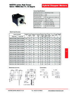
8 L It is recommended to use automatic idle-current mode, namely current automatically reduce to Isolation resistance 500 M . 60% when motor stops, so as to reduce driver heating and motor heating;. Tel: +086 0755-26434369 1 Web Site: Tel: +086 0755-26434369 2 Web Site: m542 Microstepping Driver Manual m542 Microstepping Driver Manual l It is recommended to mount the driver vertically to maximize heat sink area. Use forced cooling method to cool the system if necessary. (c) J1, J2 open circuit, J3 short circuit (d) J1, J2, J3short circuit 3. Pin Assignment and Description CW/CCW mode and active CW/CCW mode and active at low level (The fixed level) at high level (The fixed level).
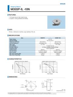
9 The m542 has two connectors, connector P1 for control signals connections, and connector P2. Figure 2: J1 and J3 jumpers for power and motor connections. The following tables are brief descriptions of the two connectors. More detailed descriptions of the pins and related issues are presented in section 4, 5, 9. Connector P2 Configurations Connector P1 Configurations Pin Function Details Pin Function Details +V Power supply, 20~50 VDC, Including voltage fluctuation and EMF voltage. Pulse signal: In single pulse (pulse/direction) mode, this input represents pulse signal, each rising or falling edge active (set by inside jumper J1); 4-5V when GND Power Ground.
10 PUL+. PUL-HIGH, when PUL-LOW. In double pulse mode (pulse/pulse) , A+, A- Motor Phase A. this input represents clockwise (CW) pulse active at high level or low level (set by inside jumper J1, J2). For reliable response, pulse width should be B+, B- Motor Phase B. PUL- longer than s. Series connect resistors for current-limiting when +12V or +24V used. The same as DIR and ENA signals. 4. Control Signal Connector (P1) Interface DIR signal: In single-pulse mode, this signal has low/high voltage levels, representing two directions of motor rotation; in double-pulse mode (set by The m542 can accept differential and single-ended inputs (including open-collector and PNP.))