Transcription of For Use with Solenoid Operated Valves Rated to …
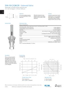
1 Vickers Switching Power Plug For Use with Solenoid Operated Valves Rated to 24V DC. EHH-AMP-702-A-*-2* Series Model Code This switching power plug is essentially a remote con- trolled on/off switch. When compared with switching E H H -A MP -70 2 -A -*- 2* relays, it gives more consistent valve response times and reduced de-energizing times. 1 2 3 Conforming to ISO 4400 (DIN 43650) interface, it has a built-in amplifier that enables the switching control 1 Type of Switch signal for hydraulic and other types of on/off Valves to A Direct switching of power supply be taken directly to the valve Solenoid , instead of via a control cabinet relay. 2 Connection Option 1 Standard PG9 cable clamp 2 Metric cable clamp Features/Benefits 3 M12x1 male connector Improved control reliability LED indicates switched on . Faster, more consistent Same connection interface 3 Design Number load switching as conventional ISO 4400.
2 21 21 Series Smaller, cooler system (DIN 43650) plug Subject to change. Installation dimensions unaltered control cabinets Protection to IP67. for design numbers 20 to 29, inclusive. Low electrically generated RoHS compliant noise Simpler, cost effective wiring of the application Electrical Block Diagram Power input+. Command C. Load signal input . 0V. Operating and Warning: Reverse polarity connection can cause damage. Performance Data Electrical Power input voltage s 24V DC (20-30V DC) including 10% maximum ripple (peak-to-peak). 24V DC nominal Reverse polarity protection No Command signal: Ri = 2,4 kV. For ON 13-30V DC. For OFF 0-6V DC. Output current: Peak 2,1A. Continuous 2A. Output voltage Typically 0,8V below input V. Load Any resistive or inductive load. Typical load: Vickers a DG4V-3 or DG4V-5. Solenoid Operated directional valve, including when used as a pilot valve. Max. switching frequency at 50% duty cycles: 350 mH load 5 Hz DG4V-3 valve sol.
3 4 Hz DG4V-5 valve sol. 3 Hz Protection IEC 529; IP67 (when correctly installed with interface seal). Isolation to VDE 0110 Group B. Electromagnetic compatibility (EMC): Emission EN 61326-2-1. Immunity EN 61326-2-1. s Connect 24V to + terminal; 0V to terminal. Mechanical Housing PA6 glass reinforced plastic (conforms to UL-94HB). Color: gray Mounting interface ISO 4400 (DIN 43650). Pin locations can be turned through 180;. polarity unchanged. Cable clamp PG9 screw type (Connection Option 1). screw type (Connection Option 2). Cable diameter 5 to 10 mm ( to dia). Wire section 0,5-1,0 mm2 (20-17 AWG). Mating connector M12x1 4 pin (Connection Option 3). Temperature, ambient range 20 to +70 C ( 4 to +158 F). Mass 0,07 kg ( lb). Typical Valve Response Times n Single Solenoid Valve Test Conditions Comparisons of response times of sample Vickers Valves (circuited as shown on the right). when controlled from remotely located power relay and EHH-AMP-702-A-20.
4 Connections A B. Response Time (ms): Valve Model Remote Switching EHH-AMP-702-A-1-21 Plug Energizing valve P T. DG4V-3 50 50. DG4V-5 50 50 Pressure: 160 bar (2320 psi). De-energizing valve Flow rate: 60 l/min DG4V-3 142 40 (16 USgpm). DG4V-5 150 45 Temperature: 55 C (131 F). n Typical data only: valve response times will vary with spool type, system pressure and flow, volume of fluid under Power supply: 24V DC. compression, supply voltage, coil temperature, etc. Input signalu: 24V DC. uS. witching signal to power plug. 2 EATON Vickers Switching Power Plug V-VLPO-MS006-E January 2009. Installation 88 ( ) 88 ( ) 3rd Angle Projection Dimensions 22. 22. and Data ( ) ( ). Dimensions shown 88 ( ). in mm (in) 39 39. ( ) ( ). 22. ( ) Solenoid Connections Solenoid Connections Solenoid Connections No connection No conn 39 34 ( ). ( ) 34 ( ) 1 (or 2) 1 (or 2). Solenoid Connections No connection 2. 2. 38 3438( ) 1 (or 2).
5 ( ) ( ). 1. 1. 2 (or 1) 2 (or 1). 2. 38. ( ). Assembly Showing Wiring Connection Points 1. WARNING 2 (or 1). Reverse polarity will destroy the connector and may cause WARNINGS load malfunction. Wire the plug for correct polarity. Wrong polarities can + : 24V DC power supply cause plug burn-out and/or : 0V. machine malfunction. C : 24V DC signal input Tighten the cable clamp to After observing the printed secure the cable. warning this adhesive label may Do not connect, or For product details see catalog V-VLPO-MS006-E. be peeled off the amplifier and disconnect the plug while discarded power is on. n nA. ll seals must be fitted correctly n at plug installation to provide PG9 cable clamp or protection to IP67 (IEC 529). cable clamp EATON Vickers Switching Power Plug V-VLPO-MS006-E January 2009 3. Assembly Connection Start-Up Procedure Option 3 - M12 Connector 1. with the plug correctly 5. E.
6 Nsure that no damage wired but not mounted to or injury will occur on the the load, provide it with machine when the valve is 24V power supply. Operated . Please refer to all safety warnings located on page 3. 2. Apply a 13V to 30V DC (24V 6. S. witch on the power nominal) command signal supply. Apply a command and check that the integral signal to: LED illuminates. Reduce ( a) illuminate the LED and, the signal to 6V DC (or open circuit) and check that ( b) energize the load ( the LED goes out. Solenoid valve). 3. If there is a malfunction of I f the LED does not illumi- the LED replace the plug. nate there is a short circuit in the load. Replace the 4. Switch off the power sup- load/load coil. ply and the command sig- nal and connect the plug to 7. S. uccessful completion of the load. Ensure that the these steps means that the interface seal is correctly plug and load are ready for fitted and clamped be- normal use.
7 Tween the mounting faces (essential for IP67 protec- 18. tion). Tighten the retaining Brown Connect with + screw. Blue Connect with - White Connect with C. Spare Parts The only spare part available is the interface seal, part number 732100. M12 Connector Ordering Procedure (1) +24V Power Order plugs by full model Notch code Model Code Part No. EHH-AMP-702-A-1-21 5995381-001. EHH-AMP-702-A-2-21 5995381-002. EHH-AMP-702-A-3-21 5995381-002. (2) Command (3) Return Seal 732100. Connector Pinout Eaton Eaton Eaton Hydraulics Business USA Hydraulics Business Europe Hydraulics Business Asia Pacific 14615 Lone Oak Road Route de la Longeraie 7 11th Floor Hong Kong New World Tower Eden Prairie, MN 55344 1110 Morges 300 Huaihai Zhong Road USA Switzerland Shanghai 200021. Tel: 952-937-9800 Tel: +41 (0) 21 811 4600 China Fax: 952-294-7722 Fax: +41 (0) 21 811 4601 Tel: 86-21-6387-9988. Fax: 86-21-6335-3912.
8 2009 Eaton Corporation All Rights Reserved Printed in USA. Document No. V-VLPO-MS006-E. January 2009.