Transcription of FOR WINNEBAGO MOTORIZED VEHICLES 310 OR 610 SERIES ...
1 SERVICE MANUALML23521 Cylinder Room Extension (With Synchronizing Cylinder)"Level Out" Room Extension (With Synchronizing Cylinder)FEATURING:HWH CORPORATION(On I-80, Exit 267 South)2096 Moscow Road | Moscow, Iowa 52760Ph: 800/321-3494 (or) 563/724-3396 | Fax: 563 ROOM EXTENSION SYSTEMS310 OR 610 SERIES LEVELING SYSTEMSWCORPORATIONHHRRFOR WINNEBAGO MOTORIZED VEHICLESS ingle Cylinder "Guided" Room ExtensionSECTION PART FOLDERHOW TO USE MANUALThis manual is written in two sections. Section 1 is the Trouble Shooting Guide. Section 2 is the figures.
2 Begin diagnosis ofthe system with Section 1, the Trouble Shooting Guide. The Trouble Shooting Guide is broken into 3 columns, Problem,Solutions and Figures. Under Problems, find the symptom you have encountered. The testing and repair for that problem isin the Solution (center) column. Diagrams for a particular Problem and Solution are in the Figures (right hand) column. Thiscolumn will direct you to the proper figure in Section 2, Figures, for a more detailed beginning your repair, it is IMPORTANT to read the CAUTIONS and NOTES AND CHECKS in the first section, TROUBLESHOOTING GUIDE.
3 In many cases this will save time and mistakes when trouble shooting a Repair Manual is offered as a guide only. It is impossible to anticipate every problem or combination of problems. Forany problems encountered that are not addressed in this manual, contact HWH Corporation for assistance. (800-321-3494)PROCEED WITH TROUBLE SHOOTING GUIDEThe room should be fully retracted before Trouble Shooting the system. If the room will not retract, use the manual retract pro-cedure on pages and sure all room locks and the manual retract winch are not engaged before trouble shooting the :This manual will work for systems with single cylinder room extensions also.
4 The only difference is the exclusion of synchronizing cylinder manual will not work if diagnosing a problem on a coach with a four cylinder room :TROUBLE !BLOCK frame AND TIRES SECURELY BEFORE CRAWLING UNDER vehicle . DO NOT USE THE LEVELINGJACKS OR AIR SUSPENSION TO SUPPORT vehicle WHILE UNDER vehicle OR CHANGING TIRES. VEHICLEMAY DROP AND OR MOVE FORWARD OR BACKWARD WITHOUT WARNING CAUSING INJURY OR ROUTING OR REROUTING HYDRAULIC HOSES AND WIRES, BE SURE THEY ARE NOT EXPOSED TO ENGINEEXHAUST OR ANY HIGH TEMPERATURE COMPONENTS OF THE PLACE HAND OR OTHER PARTS OF THE BODY NEAR HYDRAULIC LEAKS.
5 OIL MAY CUT AND PENETRATE THE SKIN CAUSING INJURY OR GLASSES ARE TO BE WORN TO PROTECT EYES FROM DIRT, METAL CHIPS, OIL LEAKS, ETC. FOLLOWALL OTHER SHOP SAFETY AND CHECKSRead and check before proceeding with Trouble Shooting : HWH CORPORATION ASSUMES NO LIABILITYFOR DAMAGES OR INJURIES RESULTING FROM THEINSTALLATION OR REPAIR OF THIS If the room extension cannot be retracted, see Figures and for temporary measures. Makesure the manual retract valves are closed before trouble Check that the oil reservoir is full with the room in the fullyretracted Batteries should read volts.
6 Batteries must be in goodcondition with no weak cells. An alternator, converter or batterycharger will not supply enough power for the system to operateproperly. Check between the positive and negative posts of the6. Proper ground of all components is critical. See the elec-trical circuit for specific grounds required. Faulty grounds,especially for the solenoid manifold or the pump assembly,may cause component damage and /or improper or erraticThis manual is intended for use by experienced mechanicswith knowledge of hydraulic and automotive electricalsystems.
7 People with little or no experience with HWHRoom Extension systems should contact HWH technicalservice (800-321-3494) before beginning. Special attentionshould be given to all cautions, wiring, and hydraulic dia-systems:JUMPER WIRES(UP TO 10 GAUGE)PRESSURE GAUGE(3500 PSI MIN.)MULTI-METER12 VOLT TEST LIGHTPROCEED WITH THE TROUBLESHOOTING STEPS ON THEFOLLOWING tools for trouble shooting the HWH room while the pump is running. This will check the batterycondition under PEOPLE AND OBJECTS CLEAR OF THE ROOM EXTENSION WHEN IT IS BEING OPERATED.
8 MAKESURE THERE IS AMPLE ROOM TO EXTEND THE ROOM The room extension can be operated any time the parkbrake is set. The ignition does not have to be in the ON orACC Make sure the leveling system operates properly. Some problems encountered with the leveling system may create a problem with the room hose end, tighten the hose end to snug plus 1/4tighten the hose end 1/3 turn (2 FLATS). If tightening anmake the hose end snug (finger tight) on the fitting, thenTightening of hose ends: If tightening a new hose end,turn (1 FLAT).TROUBLE following is a list of possible problems and solutions which might occur to room extensions.
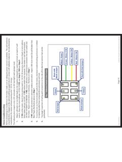
9 There will be only one powerunit / valve assembly to operate the room extension(s) and leveling system. There will be a room control switch for each roomextension. If the leveling system does not operate properly, the room extension(s) may not operate otherwise noted, the PROBLEM and SOLUTION is for either the FLAT FLOOR or DUAL CYLINDER room extensionswith a synchronizing cylinder or the SINGLE CYLINDER GUIDED room extension with any leveling 1 For coaches with two roomextensions,the pump willnot run when either room control switchis pushed toward EXTENDor coaches with one roomextension, thepump will notrun when the room control switch is pushed towardEXTEND.
10 The roomcontrol switch and the harnessthrough the coach is supplied the parkbrake needs tobe set for theroom to oper-ate. The igni-tion can be the leveling system is functioning properly, that should indicate thepark brake is set, there is battery power to the relays on the pumpand that the pump is terminal B of the room extension relay for +12 power. If thereis no power, there is a problem with the connections or cable fromthe leveling system terminal D for a ground. If there is no ground present, thereis a problem with the connection at terminal D or a problem with the9000 wire in the leveling system manifold / pump there is power on terminal B and ground on terminal D,Check the 20 amp fuse in the 6100 wire.