Transcription of Fouling in Heat Exchangers - InTech - Open
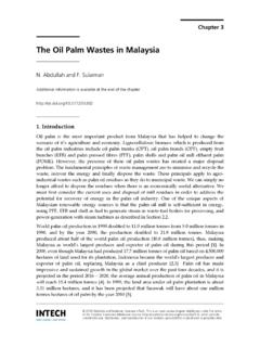
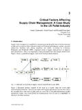
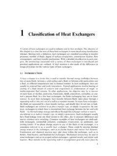
1 Chapter 3 2012 Ibrahim, licensee InTech . This is an open access chapter distributed under the terms of the Creative Commons Attribution License ( ), which permits unrestricted use, distribution, and reproduction in any medium, provided the original work is properly cited. Fouling in heat Exchangers Hassan Al-Haj Ibrahim Additional information is available at the end of the chapter 1. Introduction Fouling is generally defined as the deposition and accumulation of unwanted materials such as scale, algae, suspended solids and insoluble salts on the internal or external surfaces of processing equipment including boilers and heat Exchangers (Fig 1). heat Exchangers are process equipment in which heat is continuously or semi-continuously transferred from a hot to a cold fluid directly or indirectly through a heat transfer surface that separates the two fluids. heat Exchangers consist primarily of bundles of pipes, tubes or plate coils.
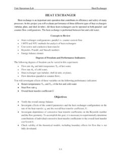
2 Figure 1. Fouling of heat Exchangers . MATLAB A Fundamental Tool for Scientific Computing and Engineering Applications Volume 3 58 Fouling on process equipment surfaces can have a significant, negative impact on the operational efficiency of the unit. On most industries today, a major economic drain may be caused by Fouling . The total Fouling related costs for major industrialised nations is estimated to exceed US$ milliard annually. One estimate puts the losses due to Fouling of heat Exchangers in industrialised nations to be about to 30% of their GDP [1, 2]. According to Pritchard and Thackery (Harwell Laboratories), about 15% of the maintenance costs of a process plant can be attributed to heat Exchangers and boilers, and of this, half is probably caused by Fouling . Costs associated with heat exchanger Fouling include production losses due to efficiency deterioration and to loss of production during planned or unplanned shutdowns due to Fouling , and maintenance costs resulting from the removal of Fouling deposits with chemicals and/or mechanical antifouling devices or the replacement of corroded or plugged equipment.
3 Typically, cleaning costs are in the range of $40,000 to $50,000 per heat exchanger per cleaning. Fouling in heat Exchangers is not a new problem. In fact, Fouling has been recognised for a long time, and research on heat exchanger Fouling was conducted as early as 1910 and the first practical application of this research was implemented in the 1920 s. Technological progress in prevention, mitigation and removal techniques in industrial Fouling was investigated in a study conducted at the Battelle Pacific Northwest Laboratories for the Department of Energy. Two hundred and thirty one patents relevant to Fouling were analysed [3]. Furthermore, great technical advance in the design and manufacture of heat Exchangers has in the meantime been achieved. Nonetheless, heat exchanger Fouling remains today one of the major unresolved problems in Thermal Science, and prevention or mitigation of the Fouling problem is still an ongoing process.
4 Further research on the problem of Fouling in heat Exchangers and practical methods for predicting the Fouling factor, making use in particular of modern digital techniques, are still called for. One significant and clear indication of the relevance and urgency of the problem may be seen in the current international patent activity on Fouling (Table 1). Country No. of Patents % of Patents 147 Germany 22 Japan 21 Sweden 9 Switzerland 8 Other 24 Total
5 231 Table 1. International Patent Activity [4] Major detrimental effects of Fouling include loss of heat transfer as indicated by charge outlet temperature decrease and pressure drop increase. Other detrimental effects of Fouling may also include blocked process pipes, under-deposit corrosion and pollution. Where the Fouling in heat Exchangers 59 heat flux is high, as in steam generators, Fouling can lead to local hot spots resulting ultimately in mechanical failure of the heat transfer surface. Such effects lead in most cases to production losses and increased maintenance costs. Loss of heat transfer and subsequent charge outlet temperature decrease is a result of the low thermal conductivity of the Fouling layer or layers which is generally lower than the thermal conductivity of the fluids or conduction wall.
6 As a result of this lower thermal conductivity, the overall thermal resistance to heat transfer is increased and the effectiveness and thermal efficiency of heat Exchangers are reduced. A simple way to monitor a heat transfer system is to plot the outlet temperature versus time. In one unit at an oil refinery, in Homs, Syria, Fouling led to a feed temperature decrease from 210 C to 170 C. In order to bring the feed to the required temperature, the heat duty of the furnace may have to be increased with additional fuel required and resulting increased fuel cost. Alternatively, the heat exchanger surface area may have to be increased with consequent additional installation and maintenance costs. The required excess surface area may vary between 10-50%, with an average around 35%, and the additional extra costs involved may add up to a staggering to times the initial purchase price of the heat Exchangers .
7 With the onset of Fouling and the consequent build up of Fouling layer or layers, the cross sectional area of tubes or flow channels is reduced. In addition, increased surface roughness due to Fouling will increase frictional resistance to flow. Such effects inevitably lead to an increase in the pressure drop across the heat exchanger , which is required to maintain the flow rate through the exchanger , and may even lead to flow blocks. Experience with pres-sure drop monitoring has shown, however, that it is not usually as sensitive an indicator of the early onset of Fouling when compared to heat transfer data; thus pressure drop is not commonly used for crude preheat monitoring. In situations where significant swings in flow rates are experienced, flow correction can be applied to both pressure drop and to heat transfer calculations to normalise the data to a standard flow.
8 Different Fouling deposit structures can lead to under-deposit corrosion of the substrate material such as localised Fouling , deposit tubercles and sludge piles. The factors that are most likely to influence the probability of under-deposit corrosion include deposit composition and its porosity and permeability. Even minor components of the deposits can sometimes cause severe corrosion of the underlying metal such as the hot corrosion caused by vanadium in the deposits of fired boilers [5]. Fouling is responsible for the emission of many millions of tonnes of carbon dioxide as well as the use and disposal of hazardous cleaning chemicals. Data from oil refineries suggest that crude oil Fouling accounts for about 10% of the total CO2 emission of these plants. Wastes generated from the cleaning of heat Exchangers may contain hazardous wastes such as lead and chromium, although some refineries which do not produce leaded gasoline and which use non-chrome corrosion inhibitors typically do not generate sludge that contains these constituents.
9 Oily wastewater is also generated during heat exchanger cleaning. MATLAB A Fundamental Tool for Scientific Computing and Engineering Applications Volume 3 60 The factors that govern Fouling in heat Exchangers are many and varied. Of such factors some may be related to the feed properties such as its chemical nature, density, viscosity, diffusivity, pour and cloud points, interfacial properties and colloidal stability factors. The chemical nature of the feed in particular can be an important factor affecting to a large degree the rate and extent of Fouling . This includes the chemical composition of the feed and the stability of its components and their compatibility with one another and with heat exchanger surfaces as well as the presence in the feed of unsaturated and unstable compounds, inorganic salts and trace elements such as sulphur, nitrogen and oxygen.
10 The feed storage conditions and its exposure to oxygen on storage in particular can in most cases also affect materially the rate and nature of Fouling . Other factors of equal importance to the feed properties may be related to operating conditions and equipment design, such as feed temperature, bulk fluid velocity or flow rate, heat exchanger geometry, nature of alloy used and wettability of surfaces where Fouling occurs. The rate of Fouling is feed temperature dependent with different rates of Fouling between the feed inlet and outlet sides of the heat exchanger . In a shell and tube heat exchanger , the conventional segment baffle geometry is largely responsible for higher Fouling rates. Uneven velocity profiles, back-flows and eddies generated on the shell side of a segmentally-baffled heat exchanger results in higher Fouling and shorter run lengths between periodic cleaning and maintenance of tube bundles.