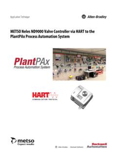
Transcription of FOUNDATION Fieldbus Design Considerations …
1 Reference ManualPlantPAx Process Automation System: FOUNDATION Fieldbus Design ConsiderationsCatalog Numbers 1757-FFLDx, 1757-FFLDCxImportant User InformationSolid-state equipment has operational characteristics differing from those of electromechanical equipment. Safety Guidelines for the Application, Installation and Maintenance of Solid State Controls (publication available from your local Rockwell Automation sales office or online at ) describes some important differences between solid-state equipment and hard-wired electromechanical devices. Because of this difference, and also because of the wide variety of uses for solid-state equipment, all persons responsible for applying this equipment must satisfy themselves that each intended application of this equipment is no event will Rockwell Automation, Inc.
2 Be responsible or liable for indirect or consequential damages resulting from the use or application of this examples and diagrams in this manual are included solely for illustrative purposes. Because of the many variables and requirements associated with any particular installation, Rockwell Automation, Inc. cannot assume responsibility or liability for actual use based on the examples and patent liability is assumed by Rockwell Automation, Inc. with respect to use of information, circuits, equipment, or software described in this of the contents of this manual, in whole or in part, without written permission of Rockwell Automation, Inc., is this manual, when necessary, we use notes to make you aware of safety , Rockwell Software, Rockwell Automation, RSLogix 5000, RSNetWorx, FactoryTalk View SE, FactoryTalk AssetCentre, PlantPAx Process Automation System, RSFieldbus, FactoryTalk View, FactoryTalk View Studio, Logix5000, Integrated Architecture, Encompass, RSNetWorx for ControlNet, Logix5000, RSLinx, RSLinx Classic, and TechConnect are trademarks of Rockwell Automation, not belonging to Rockwell Automation are property of their respective.
3 Identifies information about practices or circumstances that can cause an explosion in a hazardous environment, which may lead to personal injury or death, property damage, or economic : Identifies information about practices or circumstances that can lead to personal injury or death, property damage, or economic loss. Attentions help you identify a hazard, avoid a hazard, and recognize the consequenceSHOCK HAZARD: Labels may be on or inside the equipment, for example, a drive or motor, to alert people that dangerous voltage may be HAZARD: Labels may be on or inside the equipment, for example, a drive or motor, to alert people that surfaces may reach dangerous information that is critical for successful application and understanding of the Automation Publication RSFBUS-RM001A-EN-P - June 20113 Table of ContentsPrefaceIntroduction.
4 7 What is a FOUNDATION Fieldbus Network? .. 7 Required Equipment.. 8 Additional Resources .. 12 Chapter 1 Plan Your Network ArchitectureIntroduction .. 13 Fieldbus Network Topologies .. 13 Partition a Network .. 18 Signal Considerations .. 19 Cable Attenuation.. 19 Signal Distortion versus Capacitance .. 20 Power and Grounding Considerations .. 21 Power Supplies .. 21 Power Conditioning .. 22 Signal Wire Polarity .. 22 Grounding .. 23 EtherNet/IP Considerations .. 24 Establishing Connections .. 25 Assigning IP Addresses and Subnet Masks .. 26 Using a Managed Switch .. 27 ControlNet Considerations .. 28 Scheduling Data Communication.
5 29 Using RSNetWorx Software and ControlNet Setup Tool.. 29 Redundancy Considerations .. 30 Redundant Power Supplies and H1 Segments .. 31 Chapter 2 Basic Usage of Function BlocksIntroduction .. 33 Basic Function Blocks .. 34 Function Block Parameters .. 36 Parameter Status .. 37 MODE Block Parameter.. 38 Mode Types.. 38 Function Block Set Up .. 40 Resource Block .. 40 Transducer Block.. 43 Analog Input (AI) Block .. 44 Analog Output (AO) Block .. 45 Discrete Input (DI) Block .. 45 Discrete Output (DO) Block .. 46 PID Control Block .. 46 Distributed Function Blocks .. 47 Differences Between Configuration and Calibration.
6 48 Calibration Parameters in the Transducer Block .. 484 Rockwell Automation Publication RSFBUS-RM001A-EN-P - June 2011 Table of ContentsVirtual Communication Relationships (VCRs) .. 49 VCR Classes .. 49 BNU Class .. 50 QUU and QUB VCR Classes .. 52 Chapter 3 Plan and Configure a Fieldbus SystemIntroduction .. 53 Layout Sizing.. 53 Network Basics .. 54 Create an Application.. 57 Create a New RSFieldbus Project .. 57 Change Device Class to Back-up LAS .. 65 Initialize Communication and Associate the Linking Device .. 66 Assign Tags .. 69 Add Function Blocks.. 70 Create a Fieldbus Control Strategy .. 72 Link Blocks .. 74 Download the Configuration.
7 76 Initiate a ControlLogix Control Strategy .. 78 Add the Bridge Module .. 83 Add the Linking Device .. 85 Edit the PID Regulatory Routine.. 88 Determining Bad Quality or Loss of Input .. 96 Test the PID Loop .. 99 Set Up FactoryTalk View Software.. 99 Add Device to the FFLDC ControlNet Setup Tool .. 100 Naming Conventions .. 102 Device Addressing .. 103 PID Guide .. 104 Simple PID.. 104 Cascade PID .. 106 Feed Forward PID .. 108 Chapter 4 Visualize Fieldbus Instrument DataIntroduction .. 111 Add-On Instruction Set Up .. 113 Configuring RSLogix 5000 with an Add-On Instruction .. 113 Data Types and Add-On Instructions .. 115 Programs and Routines.
8 115FF_Device Routine .. 116 MainRoutine .. 117 Pre-designed FactoryTalk View SE Faceplates .. 118 Install Files into FactoryTalk View Studio Software.. 119 Insert Global Object to Link Data .. 119 Global Objects Attributes .. 124 Rockwell Automation Publication RSFBUS-RM001A-EN-P - June 20115 Table of ContentsFaceplate Tabs .. 125 Operator Tab .. 126 Maintenance Tab.. 128 Engineering Tab.. 129 Trend Tab .. 130 Alarm Configuration Tab .. 130 Alarms Tab .. 131 FactoryTalk AssetCentre Software Multi-vendor Options.. 132 Chapter 5 Startup and MaintenanceIntroduction .. 133 Recommended Tools .. 133 Signal Analysis .. 134 Device Recovery .. 136 Device Replacement.
9 136 Interoperability .. 136 Interchangeability .. 137 Alarms .. 137 Set and Reset .. 137 Maintain the User Name and Password .. 138 Reset the User Name and Password .. 140 Logout .. 140 Linking Device Logs .. 141 Web Server Log .. 141 Linking Device Log .. 142 Advanced Diagnostics Module .. 143 Diagnostic Blocks .. 143 Network Checklist .. 143 Chapter 6 TroubleshootingIntroduction .. 147 Manufacturer s Documentation .. 147 Common Anomalies .. 147 Signal Anomalies .. 149 Wiring Guidelines .. 149 Cable Checkout .. 150 Network and Segment Checkout .. 150 Power and Grounding Anomalies .. 151 Shielding Options .. 152 Linking Device Anomalies.
10 156 Linking Device Does Not Appear in the HSE Live List .. 156 Linking Device Does Not Appear in the H1 Live List .. 158 Linking Device Blinks On and Off in the H1 Live List.. 160 Function Block Anomalies .. 1616 Rockwell Automation Publication RSFBUS-RM001A-EN-P - June 2011 Table of ContentsAppendix AParameter StatusIntroduction .. 163 Composition of Status .. 163 Appendix BThird-party Device InformationIntroduction .. 165 GlossaryIndexRockwell Automation Publication RSFBUS-RM001A-EN-P - June 20117 PrefaceIntroductionThe purpose of this reference manual is to provide an overall framework of the concepts and Design Considerations for using your FOUNDATION Fieldbus network in a PlantPAx Process Automation System.


