Transcription of FPE-2019-30 SUBJECT: DODGE CUMMINS 5.9L & 6.7L …
1 SUBJECT: DODGE CUMMINS & cylinder HEAD INSTALLATION AND VALVE LASH ADJUSTMENT FPE-2019-30 February, 2021 Page 1 of 5 P/N S: FPE-61-10005 (-HD), FPE-60-10006, FPE-61-10007 (-HD), FPE-61-10008, FPE-61-10009 (-HD) NOTE: Always reference the appropriate CUMMINS factory manual for your specific engine. Variances exist among different models of engine configurations. The instructions below should only be considered as guidelines for the installation. cylinder HEAD INSTALLATION PROCEDURE Street heads (FPE-61-10005, FPE-61-10007) and Street HD heads (FPE-61-10005-HD, FPE-61-10007-HD, FPE-61-10009-HD): STEP 1: Install the cylinder head gasket.
2 A new gasket must be used, never re-use an old gasket. NOTE: For Street FPE-61-10005 and Street HD heads FPE-61-10005-HD we recommend CUMMINS 3958645 head gasket. For VP Street FPE-61-10009 and Street HD heads FPE-61-10009-HD we recommend the use of CUMMINS 3977063 head gasket. For Street FPE-61-10007 and Street HD heads FPE-61-10007-HD we recommend CUMMINS 4932210 head gasket. STEP 2: Place the cylinder head on the block, properly seat it into the dowels. Use caution when handling the cylinder head. STEP 3: Lubricate the threads of the head mounting bolts with clean engine oil.
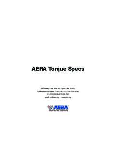
3 STEP 4: Tighten the cylinder head cap screws in the sequence illustrated. torque Values (stock CUMMINS head bolts): Step 1 90 N-m 66 ft-lb Step 2 90 N-m 66 ft-lb Step 3 - Rotate 90 degrees NOTE: The torque values above are provided for stock CUMMINS bolts. The use of high-performance studs or fasteners may require substantially higher torque values. Reference the fastener manufactures recommendations. STEP 5: Install Rocker Lever Gaskets, Housing, and Valve Cover. torque all bolts to 24 N-m (212 in-lbs) FPE-2019-30 February, 2021 Page 2 of 5 cylinder HEAD INSTALLATION PROCEDURE (Performance heads Only with fire rings and fire ring gasket FPE-61-10006, FPE-61-10008): NOTE: The Performance Head is supplied with fire rings and head gasket.
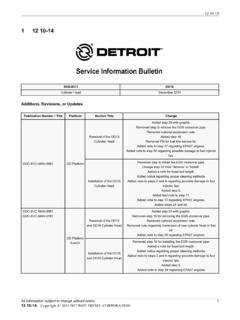
4 Use only the fire rings and gasket supplied with the head. STEP 1: Place the head gasket on the block STEP 2: Orient the fire ring weld seams as shown at right. Front and rear cylinder ring seams should face directly outward (Front and Back). Cylinders 2-5 should face sideward, within the lines shown in green. STEP 3: Inspect all alignment dowels in the block. If any are damaged, replace with CUMMINS P/N 3902343. Carefully set the head onto the block, ensuring that the head is fully seated onto the block. STEP 4: Install studs into the block per the manufacturers guidelines.
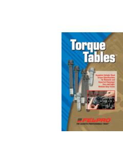
5 Using an ARP thread lubricant, such as ultra- torque , lubricate the top side of the washer, bottom of the nut, and threads of the studs. Install washes and nuts onto each of the studs. NOTE: We recommend the use of Haisley Machine L19 studs or ARP 625 s. ARP 2000 series studs are not adequate for use in fire ring head configurations. STEP 5: torque in the proper sequence as shown at right. torque as recommended by the stud manufacturer. STEP 6: Install all injectors, starting the with the two bolts that hold the injector down first, but do not tighten them.
6 Install the crossover torque to 39 ft-lbs. torque the injector hold-downs to 89 in-lbs. FPE-2019-30 February, 2021 Page 3 of 5 Front Back STEP 7: Lubricate both ends of the push tubes and install them, making sure they are fully seated into the tappet. STEP 8: Lubricate the tops of the valves and re-install the OEM rocker bridges with the indicating marks (dots) facing the exhaust side OR install Fleece Performance rocker bridges (FPE-BRAB-C1). STEP 9: Lubricate the tops of the bridges and install the rocker arm assemblies, torque OEM bolts to 27 ft-lbs.
7 STEP 10: Lash valves per procedure on page 5. STEP 11: Install lower valve cover and injector harness. NOTE: The rear of the lower valve cover will require modification for the stud clearance. Reference ARP instructions included with the studs. STEP 12: Prepare to start and run the engine. This will be performed without coolant in the system. Start the engine and allow it to idle until the oil temperature reaches 180F. Shut off the engine. NOTE: Oil temperature is most easily measured using an infrared thermometer on the oil filter housing.
8 STEP 13: Remove injector harness and lower valve cover. Remove exhaust rockers. STEP 14: Re- torque all studs. Starting at 100 ft-lbs and increasing in 20 ft-lb increments up to 10 ft-lb below the stud manufacturer s hot torque spec. STEP 15: Re-install exhaust rockers. torque to 27 ft-lbs. STEP 16: Re-lash valves as shown on page 5. Valve lash will have changed due to compression of the fire rings. STEP 17: Install lower valve cover, injector wiring, and upper valve cover. Add clean coolant and check for leaks. FPE-2019-30 February, 2021 Page 4 of 5 FPE-2019-30 February, 2021 Page 5 of 5 VALVE LASH PROCEDURE: NOTE: To obtain accurate readings, valve lash measurement and adjustments should only be performed when the engine coolant temperature is less than 60 degrees C (140 degrees F).
9 STEP 1: Disconnect negative battery cables STEP 2: Remove cylinder head cover. STEP 3: Using the crank shaft bearing tool [Fleece P/N FPE-CCBT), rotate crankshaft to align damper TDC mark to 12:00 o clock position. a. If both number 1 cylinder rocker levers are loose, continue to next step. b. If both number one rocker levers are not loose, rotate crankshaft 360 degrees. STEP 4: With the engine in this position, valve lash can be measured at the following rocker arms: Intake 1-2-4 / Exhaust 1-3-5. Measure the valve lash by inserting a feeler gauge between the rocker arm socket and crosshead.]
10 Refer to VALVE LASH LIMIT CHART for the correct specifications. If the measurement falls within the limits, adjustment/resetting is not necessary. If measurement finds the lash outside of the limits, adjustment is required. VALVE LASH LIMIT CHART INTAKE EXHAUST MINIMUM mm ( in.) mm ( in.) MAXIMUM mm ( in.) mm ( in.) NOTE: If measured valve lash falls within these specifications, no adjustment is necessary. Engine operation within these ranges has no adverse effect on performance, emissions, fuel economy or level of engine noise.