Transcription of FPGA Implementation of an Advanced Traffic Light ...
1 ISSN: 2278 1323 International Journal of Advanced Research in Computer Engineering & Technology (IJARCET) Volume 1, Issue 7, September 2012 1 All Rights Reserved 2012 IJARCET Abstract Traffic lights are the signaling devices used to manage Traffic on multi-way road. These are positioned to control the competing flow of the Traffic at the road intersections to avoid collisions. By displaying lights (red, yellow and green), they alternate the way of multi-road users. The Implementation of Traffic Light Controller can be through a Microcontroller, Field Programmable Gate Array or Application Specific Integrated Circuit. FPGA Implementation is advantageous over ASIC and microcontroller; number of IO ports and performance compared to microcontroller and Implementation with FPGA is less expensive compared to ASIC design.
2 This paper presents the FPGA implemented low cost Advanced TLC system using ChipScope Pro and Virtual Input Output. The TLC implemented is one of the real and complex signaling lights in Kingdom of Bahrain, for pedestrian way included four roads and sensors and camera assisted motorway. The system has been implemented in hardware using Spartan-3E FPGA. Index Terms ChipScope Pro, Virtual Input Output, Integrated Controller, Field Programmable Gate Array. I. INTRODUCTION FPGA is an Integrated Circuit consisting of an array of uncommitted elements; interconnection between these elements is user-programmable. Using Random Access Memory, high density logic is provided. FPGA is advantageous compared to microcontroller in terms of number of IO (input & output) ports and performance.
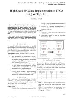
3 FPGA, an inexpensive solution compared to ASIC design; is effective with respect to cost in the case of production of large number of units but for fabrication in small number of units it is always costly and time consuming. The Design flow of FPGA shown in Fig. 1 is used to implement the Traffic Light controller using FPGA. The circuit description can be done using HDLs, followed by the functional simulation and synthesis. The design flow is followed till the timing simulation and then the generated file is downloaded into the target device (FPGA). Verilog is used as HDL for circuit description to code the TLC module. Verilog HDL is used because of the difficulty in writing a VHDL code which has to integrate the source code, ChipScope Pro-Integrated Controller (ICON) and Virtual Input Output (VIO).
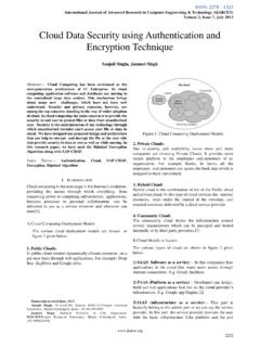
4 B. Dilip, Department of ECE, MVGR College of Engineering, Vizianagaram, India, Ph: 9963414948. Y. Alekhya, Department of ECE, MVGR College of Engineering, Vizianagaram, India. P. Divya Bharathi, Department of ECE, MVGR College of Engineering, Vizianagaram, India. II. TLC FLOW CHART The Flow Chart shown in Fig. 2 illustrates the actions to be taken by the road users. Initially, all RED signals are ON and after few seconds, GREEN of a signal Light in one particular direction will be ON to allow Traffic in straight, right and left (left also sometimes needed) paths [2], [3]. The yellow Light is split into two phases as yellow signal1 (Y1) and yellow signal2 (Y2). Pedestrian will be OFF in yellow signal1 (Y1) and pedestrian will be ON in yellow signal2 (Y2) so as to allow the pedestrians to cross the road [4].
5 Fig. 1 FPGA Design Flow At first the North Traffic will be allowed to move and then Traffic in the East, South and West direction will be allowed to move in sequence. The advantage of writing Traffic Light Controller program is that in a program, modifications as per requirements can be done easily , suppose the Traffic on main road should be allowed for more time and for side roads the Traffic should be allowed for less time; then the clock is divided in such a way that for main road the clock period will be more and for side roads the clock period will be less, this is because the main road Traffic is heavy when compared to the side road Traffic [5]. In general TLC System will be having three lights (red, green and yellow) in each direction where red Light stands for Traffic to be stopped, green Light stands for Traffic to be allowed and yellow Light stands for Traffic is going to be stopped in few seconds.
6 But in this paper, yellow FPGA Implementation of an Advanced Traffic Light Controller using Verilog HDL B. Dilip, Y. Alekhya, P. Divya Bharathi ISSN: 2278 1323 International Journal of Advanced Research in Computer Engineering & Technology (IJARCET) Volume 1, Issue 7, September 2012 2 All Rights Reserved 2012 IJARCET Light is split into two phases and are included in the signaling lights along with red and green lights in order to indicate that in the first phase of yellow Light , pedestrian will be OFF and in the second phase, pedestrian will be ON. Fig. 2 TLC Flow Chart The sequential order of the flow chart helps the programmer in the design regarding the flow of the program. North/ south-bound Traffic will start with a green signal Light while all the other lanes being red, the Traffic will be stopped.
7 After a predetermined time, the north/south Traffic Light turns yellow and then to red, allowing the east/west signal Light to be green and the same sequence as the north/south-bound Traffic is followed. The system will continue to be in this loop until an indication of a vehicle in a left turn lane occurs. When the signal Light turns yellow, the controller scans the inputs. If high, then the program will jump to a subroutine which has a different Light sequence. This sequence controls the main lights along with the left turn lights. After completion of the subroutine sequence, the program returns to the main loop. The flow chart can be applied to any number of road structures. In this paper, a four road structure is considered in which the four directions labeled with four labels namely North, South, East and West.
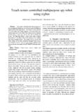
8 Each Traffic lane has set of three Traffic Light signals, Red, Yellow, and Green , which operates similar to genera signaling lights , it changes from red to green and then to yellow and after that back to red signal. III. STATE DIAGRAM The TLC state diagram shown in Fig. 3 illustrates that whenever cnt=00 and dir=00,then green Light in north direction will be ON for few seconds and red signal Light in all other directions namely west, south and east will be ON. When cnt=01 and dir=00 then yellow Light (y1) will be ON for few seconds and when cnt=01 yellow Light (y2) and pedestrian north will be ON and then dir is incremented by one and cnt is assigned to zero. So when cnt=00 and dir=01, the green Light in east direction will be ON for few seconds and all red lights in other directions be ON.
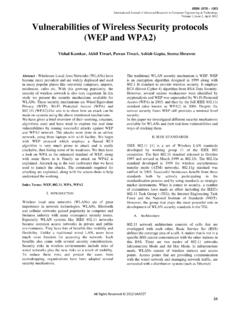
9 ISSN: 2278 1323 International Journal of Advanced Research in Computer Engineering & Technology (IJARCET) Volume 1, Issue 7, September 2012 3 All Rights Reserved 2012 IJARCET Fig. 3 TLC State Diagram Table I. Terms used in State Diagram Whenever cnt=01 and dir=01 then yellow Light (y1) will be ON for few seconds and when cnt=01 yellow Light (y2) and pedestrian east will be ON and then dir is incremented by one and cnt is assigned to zero. So whenever cnt=00 and dir=10, the green Light in south direction will be ON for few seconds and all red lights in other directions will be ON. Whenever cnt=01 and dir=10 then yellow Light (y1) will be ON for few seconds and when cnt=01 yellow Light (y2) and pedestrian south will be ON and then dir is incremented by one and cnt is assigned to zero.
10 So whenever cnt=00 and dir=11, the green Light in west direction will be ON for few seconds and all red lights in other directions will be ON. Whenever cnt=01 and dir=11 then yellow Light (y1) will be ON for few seconds and when cnt=01 yellow Light (y2) and pedestrian west will be ON and then dir is assigned to 00 and cnt is assigned to zero. This sequence repeats and the Traffic flow will be controlled by assigning time periods in all the four directions. Table I specifies the abbreviations used in TLC state diagram. Labeling for each lane is done by assigning the direction label in order to distinguish the outputs from each other with their states. In the Traffic Light controller program there will be two inputs namely clock and reset.