Transcription of Fracture Analysis, a Basic Tool to Solve Breakage Issues
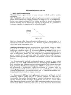
1 Fracture analysis , a Basic Tool to Solve Breakage Issues Technical Information Paper TIP 201 Issued: November 2004 Supercedes: August 2000 Toshihiko Ono Corning Japan K. K., Shizuoka Technical Center 12117, Obuchi, Osuka, Ogasa, Shizuoka, 4371397, Japan R. A. Allaire Corning Incorporated, Science and Technology Corning, NY, 14831, USA Biography T. Ono received his B. S. and M. S. degrees in inorganic chemistry from Nagaoka University of Technology, Niigata, Japan, in 1988 and 1990, respectively. In 1990, he joined the Shizuoka Technical Center of Corning Japan K. K. where he has been engaged in research and development of the finishing technologies of LCD glass substrate and other glasses. He has also proided extensive Fracture analysis support to resolve Breakage problems in Customer processes. Abstract Breakage of glass substrates in LCD manufacturing processes can cause serious problems of productivity and product quality/reliability.
2 It is known that the mechanism associated with Breakage is crack propagation by tensile stress concentration at a damaged point on the glass, which serves as an origin of the Breakage [1]. Elimination of Breakage requires the elimination of the origin and/or reducing the tensile stress. However, this solution can be applied only if location of origins and the kind of the tensile stresses are known. Fracture analysis can provide information of both the tensile stress and the origin of Breakage [2, 3]. This analytical technique gives important information in determining mechanism of Breakage , such as direction of crack propagation, type of the stress, direction of impact and friction, location of the origin. All important information is "memorized" on the broken pieces and can be obtained through microscopic observation. A process where an origin is created is often different from the process where tensile stress is applied.
3 The Breakage mechanism can be understood by combining the information from Fracture analysis with process information. The analysis method will be explained using actual cases. Also, the application of the method for optimization of cell-cutting process will be explained. Glass Breakage The mechanism of glass Breakage is that crack propagates by tensile stress that concentrated at the origin, which is a small damage as cracks on the glass surface, or in the glass body. The relation of the failure stress and size of origin is explained with Eq. 1 [4], TIP 201 | 2 where Y is constant depending on the crack and sample shape, KIC is Fracture toughness, and c is crack size. Glass having larger crack size, c, could broken at lower failure stress. Although the stress applied for glass is lower than the failure stress, crack can be propagated in the atmospheric condition, especially by water.
4 This phenomenon is called Subcritical Crack Growth (SCG) caused by stress corrosion, in which the molecular of water cut the Si-O bonding chemically [5]. The durability of the stress corrosion of glass is indicated with n, crack growth parameter. The glass having large n value is durable for SCG, means has long life reliability. The reliability of several kinds of LCD substrate was studied with Gulati et al, and Code 1737 has the highest n value, has long life reliability entire the LCD substrates [6]. 1. Origin Origins are typically generated by such mechanisms as indentation, impact, or friction during LCD processes. Actually, there are many opportunities to generate these damages during LCD manufacturing. Indentation damage is irregularly generated when substrates are clamped or chucked on process stages where foreign particles, especially glass particles, are present.
5 Therefore, once the Breakage occurs, appropriate cleaning of the glass chips, etc. in the process is essential to prevent secondary Breakage . Size of the damage as crack by indentation has been studied using Vickers point indentation [7]. The general relation between crack size and load is explained with Eq. 2, ICKPc =23 (2) where c is crack size, P is load, KIC is Fracture toughness. is a constant which relates to the material properties and geometry of indenter. Damage by impact, which is principally the same as indentation but loading speed is much faster than that of indentation, is generated mainly on the substrate edge by rapid contact with the supporting rods of the cassette or the alignment pins. This damage is easily generated because stress is localized by point contact. Friction damage is created when placing glass into cassettes, rubbing with the alignment pins, and sliding on the lithography stage.
6 This damage mode usually occurred after impact when the loading direction of the impact is not perpendicular to the surface or edge. When the friction damage is created, it can often be invisible, but becomes visible after acid etching. Stress Tensile stress is the force needed to propagate damage during substrate Breakage . Actually, thermal and mechanical stresses are main sources of tensile stress in the LCD process. Thermal stress for the crack propagation is generated when a heated glass substrate is cooled, which can create tensile stress along the substrate edge. The magnitude of the stress is a function of temperature difference, T, as shown in Eq. 3 [8], )1( =TE (3) where is Coefficient of Thermal Expansion (CTE), E is Young s modulus, T is temperature difference between inside and surface of the glass, is Poisson s ratio. is a constant that depends on Bio s constant that relates to the thermal conductivity of the glass and thermal diffusibility of coolant.
7 The constant is when the coolant is air. In addition, CTE mismatch between glass and deposited film material increases the magnitude of stress. Mechanical stress is usually due to bending during handling of the substrate, which is generated when flat glass substrate is warped, frequently due to deposited film substrate CTE mismatch. Bending stress is also generated when warped substrates become flat by vacuum chucking, or clamping. Panel sag during handling also generates bending stresses. Tensile stress by bending is generated not only at the edges, but also at glass surfaces. The tensile stress created by bending can be also calculated with Eq. 4 [9], 22twa = (4) where w is uniform load, a and t are short edge length and thickness of the glass substrate, respectively. is the constant which decided ratio of short/long edges length. Another source of mechanical stress is centrifugal stress by rotation at spin-drying or spin-coating processes.
8 Stress increases with substrate size and with rotational speed. In general, the failure stress has been used to evaluate mechanical strength of glass. However, the failure stress is strongly influenced by the size of the origin (non-conformity) on the glass substrate as indicated with Eq. 1. Understanding origin size and mechanism of Breakage is useful information for identifying and eliminating Breakage during LCD process. In the actual case, glass can be broken under the failure stress as calculated with Eq. 1 due to the residual stress created by damage such as impact or friction. These residual stresses accelerates the crack opening. cKYIC1= (1) TIP 201 | 3 Fracture analysis When glass is broken, footprints of cracks are memorized on the Fracture surfaces. These footprints map the Fracture event and are strongly related to the origin creation, crack propagation and applied stress.
9 Fracture analysis is structured with two parts, (1) observe the footprints on Fracture surface to bring the information of origin and tensile stress, and (2) analyze the information with process information to identify the Breakage mechanism. Table 1 shows the steps of the Fracture analysis until obtaining the solution of the Breakage issue [10]. Table 1. Process steps of Fracture analysis A. Obtain information from glass surface Forking, Hertzian cone, Chatter mark, Residue B. Obtain information from Fracture surface Wallner lines, Hackle marks, Mirror region, Sharra scarp, Origin C. Process information Contact point/material, Contact speed/direction, Thermal cycle, especially cooling condition, Breakage loss/trend D. Permanent Solution Fracture analysis has been applied to various glass breakages events encountered in LCD manufacturing processes, and has provided enough information to identify where the Breakage originated and how the flaw propagated.
10 Source of the information is on two surfaces, glass and Fracture surfaces as shown A and B in Table 1. The details of information taken with the Fracture analysis is well summarized in references [1-3, 10,12,13]. Brief explanation of these information are performed below. A. Information from Glass Surface Forking: Forking is crack branching. Qualitative magnitude of applied stress can be known from number of cracks forking as shown in Fig. 1. Hertzian cone: Hertzian cone crack is created by localized impact with blunt hard object. Schematic illustration of the Hertzian cone creation is shown in Fig. 2. Fig. 2 Schematic illustration of Hertzian cone crack creation from cross sectional view. Chatter mark: Chatter marks is created by friction, and its shape indicates direction of the friction. Cracks curves concavity toward rubbing direction as shown in Fig.