Transcription of Frames values reliability and operational simplicity …
1 Electrostatic Coalescers Building on more than 25 years of combined in-house coalescer engineering experience Frames has developed its proprietary Electrostatic Coalescer design. The sizing of Frames Electrostatic Co-alescers is characterized by a clever combination of physics and empirical data that has shown to be reliable and has been proven over the years. Frames Electrostatic Coalescers are optimized to guarantee the required performance whilst keeping their size and layout cost-effective. Electrostatic Treatment Crude oil contains water and other contaminants that need to be re-moved to improve the economics of transport, limit the requirements of downstream equipment and to pre-vent negative effects on downstream refining processes.
2 The Electrotatic Coalescer that is used for this pur-pose, is one of the many products Frames offers the Oil & Gas industry. The removal of water and contaminants generally comprises of two principles: dehydration and desalt-ing. For this purpose Coalescers are applied in both upstream and downstream applications. In oilfields, the emphasis is generally on a combination of dehy-dration and desalting, whereas in refineries the focus is primarily on desalting. DEHYDRATION The first step in the removal of water from oil (dehydration) typically involves two or three phase bulk separation upstream.
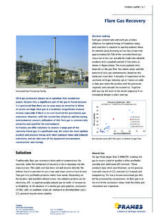
3 Electrostatic treatment is here the final separation step, applied to break up the emulsions and reduce the remaining water frac-tion. Dehydration is typically applied in Upstream applications. DESALTING Besides for dehydration, Electrostatic Coalescers are further applied for de-salting: reducing the salt content of the crude. The salts are soluble in wa-ter, so a reduction in water fraction automatically reduces the salt content. Desalting often occurs in two stages: the first stage (dehydration) is fol-lowed by a second stage (desalting), where the salts are diluted by the addi-tion of wash water between the first Coalescer (Dehydrator) and the second (Desalter).
4 The main aim of having a second stage in the sys-tem is to ensure a high dilution rate (ratio of wash water and water fraction in the crude). Dilution is necessary since dehydration alone is usually not suf-ficient to reach typical salinity values in the export crude (~10 - 100 PTB). How does it work? The Frames inlet distributor injects crude just below the electrostatic grids. Be-tween the grids the water droplets pre-sent in the crude are exposed to the electrostatic field that rearranges the (salt) ions within the droplets.
5 Droplets will then attract each other and as a result coalesce (1), grow in size and fall out (2) of the upward flowing crude. The treated crude is collected at the top of the vessel while the effluent water is collected at the bottom. Frames values reliability and operational simplicity and as such has embraced the AC-technology at the core of its Coalescer designs Typical 2-stage desalting system Product DefinitionFrames proprietary electrostatic coalescers are 2-phase separators that utilize an electrostatic field to remove water and salts from crude oil, allowing cost-effective transport and protect downstream DescriptionFrames builds on its vast experience in coalescer engineering.
6 Enabling us to give our clients a competitive advantage when it comes to cleaning crude oil. By efficiently and effectively removing undesirable water and salts, our clients are able to increase the quality of their crude oil, cut their transport costs and protect their downstream processes and of water and contaminants generally comprises two steps: dehydration and desalting. Frames coalescers are designed for both steps, and are applied in upstream as well as downstream applications. In oilfields, the emphasis is generally on a combination of dehydration and desalting, whereas in refineries the focus is primarily on Leaflet / p 1 DehydrationIn the process of removing water from oil, electrostatic treatment is typically preceded by 2-phase or 3-phase bulk separation in the upstream process.
7 Electrostatic coalescers are applied as the final separation step to break up emulsions and reduce the remaining water fraction (dehydration). This is the reason why they are typically applied in upstream coalescers are also applied for desalting in order to reduce the crude s salt content. Because salts are soluble in water, a reduction in water fraction will automatically reduce the crude s salt content. Desalting therefore often occurs in two stages: the first stage (dehydration) is followed by a second stage (desalting), where the salts are diluted by the addition of wash water between the first coalescer (dehydrator) and the second (desalter).
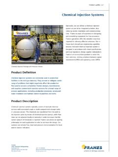
8 The main aim of having a second stage in the system is to ensure a high dilution rate (ratio of wash water and water fraction in the crude). This dilution is necessary since dehydration alone is usually not sufficient to reach typical salinity values in the export crude (~10 - 100 PTB).3D model of Frames Electrostatic CoalescerFrames Separation TechnologiesGlazenmakersweg 33449 JK WoerdenThe Netherlands+31 88 00 333 Coalescers (Dehydrators / Desalters)High-Voltage ConnectionTransformerElectrostatic GridsOil OutletCollectorCalming Baffle(for FPSO s)Inlet DistributorWater CollectorWorking principle of coalescence (1) and separation (2) inside Electrostatic CoalescerProduct Leaflet / p 2 Product DescriptionThe Frames inlet distributor injects crude just below the electrostatic grids.
9 Between the grids, the water droplets present in the crude are exposed to the electrostatic field that rearranges the (salt) ions within the droplets. Droplets will then attract each other and as a result coalesce, grow in size and fall out of the upward flowing crude. The treated crude is collected at the top of the vessel while the effluent water is collected at the Electrostatic Coalescers are designed using Alternating Current (AC). Although other types of power supply are available and promoted (DC, AC+DC), these are operationally demanding and bring significant draw-backs, for instance a tendency for arcing (short-circuiting) and electrical complexity.
10 Because Frames values reliability and operational simplicity , we have embraced the AC technology at the core of our designs. Frames inlet distributor The unique Frames inlet distributor has been specifically designed to ensure optimal (uniform) distribution of the oil-water mixture just below the grid. This results in efficient use of the electrostatic area and allows the use of smaller vessels compared to the traditional distributors used in the industry. The number of headers and their design are specifically sized for each application using design rules developed by Frames .