Transcription of Frequency Response Of Critical Components Of A …
1 Frequency Response Of Critical Components Of A hydraulic Servovalve M. Singaperumal, Somashekhar. S. Hiremath and R. Krishnakumar Department of Mechanical Engineering Indian Institute of Technology Madras Chennai - 6000 36 (India). ABSTRACT The analyzed electrohydraulic servo valve is jet pipe type, is one of the mechatronics component used for precision flow control application. The jet pipe servo valves have one movable nozzle and two collector ports, from where fluid is ducted to the main valve spool. The servovalve analyzed here is basically used in fuel control application in Variable Geometry Actuation System (VGAS) of a gas turbine engine. It consists of several precision and delicate Components .
2 For the analysis the feedback spring assembly and jet pipe assembly of jet pipe servovalve are identified and conducted direct-solution steady-state dynamic analysis to study the Response of the system for harmonic excitation. The assembly was subjected for analysis to ascertain the Response for Critical parameters like thickness of flexure tube and material for flexure tube. Key words: natural Frequency , flexure tube, servovalve, feedback spring, and precision 1. INTRODUCTION Electrohydraulic servovalve is one of the precision mechatronic Components , used in many feedback control systems, working on jet engine and fighter aircrafts. In 1950, the electrohydraulic servovalve (EHSV) was conceived; to meet the aerospace program need for a precise hydraulic flow.
3 EHSV pioneers considered using an electromechanical device to position the spool, but were limited by available electric motor and control technology. They rejected this bulky method in favour of a device using hydraulic pilot pressure to position the spool. Therefore the EHSV is an essential item of a servomechanism where fast speed of Response , high power output and working fidelity are necessary [1]. The analyzed electrohydraulic servovalve of the jet pipe type, used for precision flow control application. It consists of several precision and delicate Components . The performance of the valve depends on many parameters. During the developmental stage, it is very difficult to ascertain the functional parameters.
4 Experimentation requires the valve and its Components . Theoretical and simulation tools are available to predict the functional parameters. One of the powerful tools is solid modelling and FE simulation. Many attempts have been made in modeling the dynamic characteristics of servovalves particularly flapper type and allied Components and models of varying complexity have evolved [2-5]. The complexity required is of course dependent upon the overall system dynamic performance which should be related to the probable dynamic characteristic of the servovalve suggested by the manufacturer. Less number of literatures is available on jet pipe type.
5 A jet-pipe valve consists of a nozzle and a receiver block shown in The receiver block is having two closely spaced holes. The nozzle, or jet pipe, is arranged on a pivot so that it may be displaced from a neutral position. The jet pipe serves to convert pressure energy into the kinetic energy of a jet and directs this jet toward two receiver holes in the receiver block. When the jet of oil strikes the flat receiver block its kinetic energy is recovered in the form of pressure. If the stream is directed exactly halfway between the receiver holes, the pressure in the two holes will be equal; the differential pressure, therefore, is zero. As the jet pipe is deflected, more oil will be directed at one hole than the other, raising the pressure in that hole and decreasing the pressure on the other, and thus creating a differential-pressure output.
6 Pressure recovery in receiver holes is a function of jet pipe displacement relative to receiver plate and recovery falls off for larger jet displacements [6]. Theoretical investigation was conducted on various affecting parameters on the static pressure recovery in the receiver holes. The major parameters studied are distance between the receiver holes (web thickness), jet pipe nozzle diameter, receiver hole diameters, nozzle offset and nozzle stand-of distance [7]. Simulation study was done on pressure recovery in jet pipe servovalve [8]. The analytical and experimental investigation of a jet pipe controlled electropneumatic actuator for Frequency Response and time-domain force tracking was done [9].
7 The analyzed valve is miniature type having jet pipe and receiver diameters m, the distance between the receiver holes 1X10⁻⁵ m and spool diameter 11 X10-3 m. Many attempts have been made in modeling the dynamic characteristics of servo valves and allied Components and models of varying complexity have evolved 1,2,3,4. The complexity required is of course dependent upon the overall system dynamic performance which should be related to the probable dynamic characteristic of the servovalve suggested by the manufacturer. The analyzed servo valve is a miniature type having the jet pipe (D) and receiver hole diameters (d) as m, the distance between the receiver holes as (W) 1X10⁻⁵ m and the spool diameter (Ds) as 10X10-3 m.
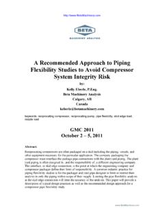
8 Operating description of jet pipe servovalve The jet pipe electrohydraulic servovalve consists of two main assemblies, a torque motor assembly representing first stage and valve assembly representing the second stage. In-between the first and second stage, there is a mechanical feedback to stabilize the valve operation. The schematic representation of the two assemblies is shown in The valve operates as follows: Electrical current in the torque motor coils creates magnetic forces on the ends of the armature. Armature and jet pipe rotates about flexure tube support. Jet pipe deflection leads to move the more oil flow to one receiver hole than the other, creates a differential pressure across the spool end.
9 Spool moves and opens pressure port Ps to one of the control port and opens the other control port to tank T . During spool movement, it pushes the feedback spring connected between the jet pipe and spool, creating restoring torque on the jet pipe. As the feedback torque becomes equal to torque from magnetic forces, the jet pipe moves back to centered position (null position). Spool stops at a position where feedback spring torque becomes equal to torque in armature. This torque balance is said to be steady state operation of the servo valve. The resulting spool position opens a specified flow passage at the ports of the second stage of the valve. Fig. 1: Schematic diagram of jet pipe assembly.
10 2. STEADY STATE DYNAMIC ANALYSIS Generally the Frequency extraction procedure performs eigenvalue extraction to calculate the natural frequencies and the corresponding mode shapes of a system. It will include initial stress and load stiffness effects due to preloads and initial conditions if *STEP, NLGEOM is used in the base state, so that small vibrations of a preloaded structure can be modeled. If initial stress effects are not included and there are no rigid body modes, stiffness matrix is positive definite; otherwise, it may not be. Negative eigenvalues normally indicate instability. The * Frequency procedure uses eigenvalue techniques to extract the frequencies of the current system.