Transcription of Frequency Response of Thin Film Chip Resistors
1 Document Number: 60107 For technical questions, contact: 04-Feb-091 VISHAY INTERTECHNOLOGY, ProductsTechnical NoteFrequency Response of thin film chip ResistorsTECHNICAL NOTEABSTRACTHigh Frequency measurements from GHz to 40 GHz wereperformed on industry standard flip chip thin film resistorsfrom Vishay thin film . The results of these measurementsare reported in this paper. A lumped circuit model ispresented that accurately predicts the Response of variouspart values and case sizes. The results of the measurementsand model are combined to demonstrate basic designguidelines for microwave thin film the industry extends products into the GHz range, anunderstanding and improvement of resistive products performance needs to be extended into this , thin film Resistors have been used in areasrequiring high-precision, long-term stability, and lowtemperature coefficient of resistance.
2 Frequencyperformance of thin film Resistors , in excess of 100 MHz,typically involves a roll-off of the impedance to eitherinductive or capacitive-dominated values, commonlyreferred to as parasitic impedance. (1)(2)(3)(4)Microwave Frequency measurements were made on variousthin film part values and case sizes. Correlation of theexperimental data to a mathematical lumped circuit modeldemonstrated a relation of parasitic impedance to case size,DC resistance, and trim style. Extrapolation of the model todifferent part values and higher frequencies was used topredict roll-off performance and demonstrate designguidelines for high- Frequency ( GHz to 100 GHz) thin thin film Resistors from 50 to 1000 wereconstructed on high performance % alumina substrateswith case sizes of 0201, 0402, and 0603, (see table 1) andtwo termination methods (i) flip chip and (ii) wrap around, seefigure 1.
3 The resistive material was physical vapor deposited(PVD) nickel-chrome (NiCr) with a 50 ppm thermalcoefficient of resistance (TCR). An optimized laser trim wasused to provide a balanced resistor with low internal parasiticeffects. The resistor element was protected with overcoatsdesigned for electrical, mechanical, and Frequency testing was performed on parts mounted toquartz test boards. Quartz test boards were chosen tominimize the contribution of the board effects at highfrequencies. The quartz test boards were fabricated usingmicrostrip technology; the RF ground plane is located on thereverse side. All parts were mounted on identical boards andtested independently, see figure 2. Wrap around parts weremounted with the resistor up and flip chip parts weremounted with the resistor down, see figures 1 and 1 - Termination styles:Left - flip chip , resistor downRight - wrap around, resistor upFig.
4 2 - Mounting on Resistors on RFgrounded quartz substrates for testingLeft - flip chip , resistor downRight - wrap around, resistor upTABLE 1 - PARAMETERS FOR DIFFERENT CASE SIZES UTILIZEDCASE SIZELENGTH (inch/mm)WIDTH (inch/mm) resistor AREA (inch2/mm2)MODEL INTERNAL COEFFICIENTSC(pF)L(nH) x x 10-30402 (wrap) Response of thin film chip Resistors technical questions, contact: Number: 601072 Revision: 04-Feb-09 Technical NoteVishayTECHNICAL NOTEFig. 3 - Lumped equivalent circuit used for modeling, a transmission line model was addedfor the resistor s landing pad and the test substrate s mounting pad effectsModelithics, Inc. was contracted to perform S-parametermeasurements. The S-parameter data was then used toextract the lumped circuit topology shown in figure 3, wherethe chip s contact pads are included in the transmission linemodel of the test substrate s mounting pads. The topologyfrom figure 3 has been used by other experimentalist, theterms are described as (i) internal capacitance as a couplingof the pads, (ii) external capacitance as a coupling to theboards ground plane, (iii) internal and external inductance asthe finite length of the resistor and pads, and (iv) internalinductance is also affected by the skin effect, or thedecreasing of the effective thickness resistor as thefrequency increases and is Frequency depedent.
5 (2)(4)(6)(7)RESULTSF igures 4 through 6 show the impedance responsenormalized to the device value for 0201, 0402 and 0603 casesizes. These graphs show that the Resistors tend to haveeither a dominant shunt capacitance, or series inductance,depending on the resistor value. These results are inagreement with other publications. (1)(8) Papers where onlyvalues lower than 100 were measured tend to correlate theobserved series inductance to the skin effect or surfaceimpedance used in waveguide and resonant cavityapplications. (2)(4)(5)(9)(10) These papers note that theincreasing impedance is proportional to the square root ofthe Frequency . (2)(4) The skin effect however does not supportthe decreasing impedance for higher resistor values. Wehave chosen instead to model the results with a lumpedcircuit mathematical representation, figure 3.
6 To model theobserved decreasing impedance a fixed internal impedancewas included in the topology (see figure 3) to describe thefinite length of the resistor and provide a mechanism for theobserved increasing impedance of lower ohm resistorvalues. (2)(4)(6)(7)The fitted results for the lumped circuit model are plotted withthe data in figures 4 to 6. The fitted model coefficient valuesare listed in table 1 and figure 7. The fitted results of partvalues above 100 are typically very good. Fitted results ofthe part values less than 100 do not completely describeall the parts, the 0201 case has a small peak at about30 GHz that is not described by the model, see inset infigure 4 - 0201 flip chipThe minor peak for the smaller parts at 30 GHz is not accurately modeled by the circuit of figure 3 (see inset). This is the smallest case size tested and had the best impedance 5 - 0402 case sizeBoth the (a) wrap and (b) flip chip terminations are plotted.
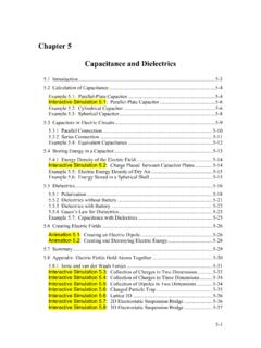
7 The flip chip outperforms the wrap termination. The 75 flip chip demonstrates the 0201 difficulty with modeling small LCCGCGC: internal shunt capacitanceL: internal inductanceR: resistanceLC: external connection inductanceCG: external capacitance to groundFrequency Response of thin film chip ResistorsTechnical NoteVishay Document Number: 60107 For technical questions, contact: Revision: 04-Feb-093 TECHNICAL NOTEP eaks are seen in all the case sizes, particularly for 100 and less. The external and internal inductive, resistive, andcapacitive (LRC) equivalent circuits, shown in figure 3, candescribe this peak mathematically. Large peaks; such aswith the 0402 wrap; are modeled very well by this circuit andsmall peaks; such as exhibited with the 0201 case size; aremore difficult to model without modifications to this 6 - 0603 flip chipThe 100 , and to some extent the 200 part, demonstrate the 0201 difficulty with modeling small peaks above 25 7 - Modeling coefficients from figure 1.
8 The large differencein impedances for case sizes clearly demonstrates theimportance to minimize the footprint of the the case size is increased the performance and thereforethe model coefficients are affected. Figure 8 plots theimpedance performance for different part values and casesizes. The smallest case size, 0201, performs better thanboth the 0402 and 0603 case sizes for all part values. Thedifferences in the 0402 and 0603 case sizes are moderateand occasionally reversed and may be related to the devicedimensions. The maximum area the resistor can cover foreach case size is given in table 1. The ratios of the resistorarea by case size (0603 : 0402 : 0201) are 1 : : Thedimension change to 0201 from 0603 or 0402 is significantand can explain the large difference in device 8 - Case size comparison of 0201, 0402, and 0603 Plot (a) is 50 , (b) 100 , (c) 500 , and (d) 1000.
9 The 0201 case size clearly out performs 0402 and 0603 case 9 - Prediction of devices from the model for (a) 0402 wrap, (b) 0402 flip chip , and (c) 0402 flip chip with L-cut trim. By extending the range of the model results indicates the presence and approximate location of the peak observed with some of the tested external modeling coefficients, figure 7, show similarresults to the case size impedance performance, figure external coefficients are clearly dependant on case sizeand part values. The smaller case size gives smallercoefficients and the inductance coefficients increase forincreasing part value while the capacitance coefficientsremain relatively constant. The internal coefficients do nothave a large dependency on size or part value; rather theiraverage values are included in table results extending beyond the measurement rangecan be used to predict the LRC peak location and 9 extends the model to 150 GHz for the 0402 casesize; (a) 50 wrap, (b) 50 flip, and the (c) 100 L-cut.
10 Thewrap termination data displays an almost complete peak; theflip and L-cut chips show different regions of the peak and itspredicted location and magnitude. The flip chip data has thereal part displaying a positive slope with an inflection point inthe imaginary data the model continues beyond these pointsand predicts a 60 GHz peak. An L-cut on a 100 flip chip hasFrequency Response of thin film chip Resistors technical questions, contact: Number: 601074 Revision: 04-Feb-09 Technical NoteVishayTECHNICAL NOTEthe imaginary part displaying a positive slope with a inflectionpoint in the real data; the model continuing beyond 40 GHzpredicts the same 60 GHz peak with a larger were tested for the 0402 case size, figure impedance Frequency Response for the flip style was lessdependant on part value from 50 to 200 . The use ofmicrostrip test boards caused the wrap around terminationground plane to be located further away from the resistorthan the flip chip .