Transcription of FRP Stair Crossovers G Stair Crossover Assembly Instructions
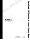
1 FRP Stair CrossoversYEARS50 CELEBRATING []HeavyMetalSAFEA rsenic Barium Cadmium Chromium Lead Mercury Nickel Selenium SilverISO9001-2008 QUALITY CERTIFIEDFACILITIES Fibergrate Composite Structures Inc. 2016 Fibergrate Composite Structures Inc. High Performance Composite Solutions Since 1966- - - - - - - - - - - - - - - - - - - - - - - - - - - - - - - - - - - - - - - - - - - - - - - - - - - - - - - - - - - - - - - - - - - - - - - - - - - STEP 1:ITEM DESCRIPTIONPART NUMBERFRP Stair Crossover - 10" Stair Crossover - 19-1/2" Stair Crossover - 29" Stair Crossover - 38-1/2" Stair Crossover - 48" Stair Crossover - 65" FRP Stair Crossover (POST Assembly ILLUSTRATION)ATTACH Stair ASSEMBLIES TO PLATFORM ASSEMBLYA) Slide channels of Stair Assembly inside of Splice Plates on Platform Assembly and line up the holes.
2 Refer to Drawing B-03060 Rev 1 dated 2/23/17 for the exact configuration of the Crossover . The illustration shown in these Instructions may vary from the Crossover you are ) For the Stair Crossovers up to and including the 48 inch (1219 mm) clearance Crossover (PN ): Install two each 1/2 x 2 hex head bolt assemblies (1/2 x 2 bolt, 2 each flat washers, and 1/2 nut) in the holes indicated. Use a flat washer under the bolt head and the nut. Torque the 1/2 inch nuts to 45 ft-lb ( N-m).Leave the holes for the guardrail posts open until Step ASSEMBLYSTAIRASSEMBLY1/2" DIAMETER HEX HEAD BOLT ASSEMBLIES{C) For the 65 inch (1651 mm) clearance Stair Crossovers (PN ): Install two each 5/8 x 2 hex head bolt assemblies (5/8 x 2 bolt, 2 each flat washers, and 5/8 nut) in the holes indicated.}
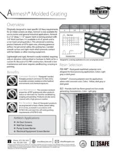
3 Use a flat washer under the bolt head and the nut. Torque the 5/8 inch nutsto 45 ft-lb ( N-m). Leave the holes for the guardrail posts openuntil Step ) Repeat for second Stair | 800-527-4043 STEP 2:ASSEMBLE HANDRAIL TO GUARDRAILSA) Attach the stainless steel handrail brackets to the 1-1/2 inch dia round handrail tubes using two #14 x 1 inch self-tapping screws per handrail bracket. The pilot holes for the screws are shop drilled into the handrail tubes. Be careful not to over-torque the screws to prevent stripping the holes. Note that you will be assembling a left hand and a right hand set of handrails for each ) Attach the handrail to the guardrail by following Details 702 and 703 in Drawing B-3060.
4 The stainless steel handrail brackets connect to the 2-1/8 inch (54 mm) post and 1-3/4 inch ( mm) rail with a 3/8 x 3 hex head bolt Assembly , flat washer, and backer plate. Apply blue thread locking compound to the bolt threads prior to installing the nuts. Torque nuts until the assemblies are tightly clamped TO GUARDRAIL Assembly #14 x 1" SELF TAPPING SCREW -2 PER HANDRAIL BRACKET (4 TOTAL)1-1/2" DIA. ROUND HANDRAIL TUBE STAINLESS STEEL HR BRACKET - 1 PER HANDRAIL TUBE (2 TOTAL)HANDRAIL BRACKETASSEMBLY DETAIL90 ELBOWPRE-DRILLED HOLE1/4" x 2-1/2" ROUND HEADBOLT ASSEMBLYHANDRAIL3/8" X 3" HEX HEAD BOLT ASSEMBLYSTAINLESS STEEL BACKER PLATEC) The 90 elbow at the top and bottom of the handrail connects to the 1-3/4 inch ( mm) square tube rail return by fitting it into the pre-drilled hole and securing it with a 1/4 x 2-1/2 round head bolt Assembly .
5 Install the round head bolt so that the nut is oriented toward the inside of the Assembly . Refer to Detail 703. Apply blue thread locking compound to the bolt threads prior to installing the nut. Torque nuts until the assemblies are tightly clamped Installation Time: 2 Man Crew, 2 HoursStair Crossover Assembly | | 800-527-4043 INSTALL GUARDRAILSA) For the Stair Crossovers up to and including the 48 inch (1219 mm) clearance Crossover (PN ): Install each Guardrail Assembly to the Crossover by sandwiching the 2-1/8 inch x 3/16 inch (54 x mm) Square Tube Post Spacers between the Guardrail Assembly and the Crossover and Installing the 1/2 inch x 5-1/2 inch hex head bolt assemblies (1/2 inch x 5-1/2 inch bolt, 2 each flat washers, and 1/2 nut) in the holes indicated.
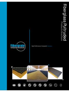
6 Where the post falls on a splice plate, use the shorter spacer. The longer spacers are for the locations where the post is bolted directly to the web of the channel. Use a flat washer under the bolt head and the nut. Hold Post Spacers in alignment with the edges of the post while torquing the nuts. Torque the nuts to 45 ft-lb ( N-m).B) For the 65 inch (1651 mm) clearance Stair Crossovers (PN ): Follow the Instructions above except use 1/2 inch x 6 inch hex head bolt assemblies (1/2 inch x 6 inch bolt, 2 each flat washers, and 1/2 nut) for installing the Guardrail ) Repeat for all six Guardrail ) For the 10 inch (254 mm) clearance Stair Crossover (PN ).
7 Connect the vertical portion of each horizontal and inclined Guardrail Assembly to each other using two each 1/4 x 4-1/2 hex head bolt assemblies (1/4 x 1-1/2 bolt, 2 each flat washers,and 1/4 nut) in the factory drilled blue thread locking compound tothe bolt threads prior to installing thenuts. Torque nuts until the assembliesare approximately 1/4 (6 mm) fromeach other. It will not be possible pull the two assemblies tightly 3:1/2" x 5-1/2" HEX HEAD BOLT ASSEMBLYPOST SPACERHORIZONTAL GUARDRAIL ASSEMBLY1/2" DIA. HEX HEAD BOLT ASSEMBLYANCHOR HOLE - 9/16" DIAMETER 4 PLACESINCLINED GUARDRAIL ASSEMBLYA) Remove the four 3 x 3 x 3/8 x 6 long angles at the bottom of the stairs by removing the two factory installed 3/8 x 1-1/2 hex head bolts at each angle.
8 Retain the bolts; discard the ) Attach the four 3 x 3 x 3/8 x 6 long angles supplied with the kit to the 1 -4 x 4 -9 x 1/2" thick FRP plate using the 3/8 x 1-1/2 long flat head bolts supplied with the kit. Note the orientation of the angles. Torque the bolts to 30 lb-ft ( N-m).STEP 5:ANCHOR Stair CROSSOVERSTEP 4:A) Prior to use, the Stair Crossover must be anchored to the supporting surface to prevent tipping. Anchor holes are 9/16 inch ( mm) diameter and located at the bottom of the Stair in four locations (see illustration on page 3). Anchoring hardware is not ) Concrete Floors: Anchor Stair Crossover to concrete floors using 4 each 1/2 diameter expansion or adhesive concrete anchors.
9 A minimum embedment of 2-1/2 is ) Wood Floors: Anchor Stair Crossover to wooden floors with four each 1/2 x 3 lag ) For other support conditions, contact a qualified engineer to develop adequate anchoring details. For installations on roofs or other areas where the supporting surface cannot be penetrated by fasteners, install the Roof Plate Kit by following Step Five ROOF PLATE KIT1'-4" x 4'-9" x 1/2" FRP PLATE(2 TOTAL)C) Attach this Assembly to the bottom of the Stair using the 3/8 x 1-1/2 removed in step 2. Torque the bolts to 30 ft-lb ( N-m).D) Before placing the finished Crossover onto the roof surface, protect the roof from abrasion following the roof manufacturer s recommendations.
10 Add ballast as required to the locations indicated in Drawing " x 1-1/2" FLAT HEAD BOLTS(8 TOTAL)COMPLETED FRP Stair Crossover WITH OPTIONAL ROOF PLATE (POST Assembly ILLUSTRATION) Stair Crossover Assembly InstructionsStair Crossover Assembly InstructionsCD876543CB21DC8=8"x2 3/16"x3/8" CHANNEL = A2 BRACE = GUARDRAIL = GUARDRAIL POST = GUARDRAIL RETURNA2=2"x2"x1/4" ANGLEBC8C8101 PLAN - FRP Crossover GRATING PLAN3'-0" BY4 DATEREFERENCE DWGS.:WRITTEN AUTHORIZATION OF FIBERGRATECOMPOSITE STRUCTURES STRUCTURES INC. DRAWING IS NOTIS THE SOLE PROPERTY OF FIBERGRATE THIS DRAWING AND ALL DESIGN INFORMATIONTO BE DISCLOSED OR COPIED WITHOUT THE 2DO NOT STACK TOLERANCESANGULARITY 2 GRATINGMOLDED+1/8,-5/16+1/8,-5/16 1/16 3/16 1/8 CIRC.