Transcription of FSP-851, FSP-851T and FAPT-851 Intelligent …
1 FSP-851, FSP-851T and FAPT- 851 intelligent photoelectric smoke sensors Installation and Maintenance Instructions This sensor must be installed in compliance with the control panel system installation manual. The installation must meet the requirements of the Authority Having Jurisdiction (AHJ). Sensors offer maximum performance when installed in compliance with the National Fire Protection Association (NFPA); see NFPA 72. GENERAL DESCRIPTION. Models FSP-851, FSP-851T and FAPT-851 are plug-in type smoke sensors that combine a photoelectronic sensing chamber with addressable-analog communica- tions. The sensors transmit an analog representation of smoke density over a communication line to a control panel. Rotary decade switches are provided for setting the sensor 's address. Two LEDs on the sensor are controlled by the panel to indicate sensor status. An output is provided for connection to an optional remote LED annunciator (P/N.)
2 RA400Z). Models FAPT-851 and FSP-851T combines a photoelectronic sensing chamber and 135 F ( C) fixed temperature heat detector. Notifier panels offer different features sets across different models. As a result, certain features of the FSP-851, FSP-851T and FAPT-851 may be available on some control panels, but not on others. The possible features available in the FSP-851, FSP-851T and FAPT-851 , if supported by the control unit are: 1. The panel controls the LED operation on the sensor . Operational modes are RED blink, RED continuous, GREEN blink, and off. 2. The remote output may be synchronized to the LED operation or controlled independent of the LEDs. Please refer to the operation manual for the UL listed control unit for specific operation of the FSP-851, FSP-851T and FAPT-851 . The FSP-851, FSP-851T and FAPT-851 require compatible addressable communications to function properly. Connect these sensors to listed-compatible control panels only.
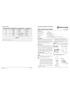
3 SPECIFICATIONS REMOTE ANNUNCIATOR. Operating Voltage Range: 15 to 32 VDC + . Standby Current: 300 A @ 24 VDC (one communication every 5. seconds with LED blink enabled) +. Max. Alarm Current (LED on): mA @ 24 VDC. UL LISTED COMPATIBLE. Operating Humidity Range: 10% to 93% Relative Humidity, noncondensing CONTROL PANEL. Operating Temperature Range: 0 to 49 C (32 to 120 F); FSP-851 3 2 3 2. 0 to 38 C (32 to 100 F); FSP-851T , FAPT-851 1 1. Height: inches (51 mm) installed in B710LP Base Diameter: inches (155 mm) installed in B710LP Base inches (104 mm) installed in B501 Base Weight: oz. (147 g).. SPACING OPTIONAL RETURN LOOP. Notifier recommends spacing sensors in compliance with NFPA 72. In low air flow +. applications with smooth ceilings, space sensors 30 feet apart. For specific informa- A78-2461-00. Figure 1. Wiring Diagram tion regarding sensor spacing, placement, and special applications, refer to NFPA 72 Caution: Do Not Loop Wire Under Terminal 1 or 2.
4 Or the System smoke Detector Application Guide, available from Notifier. Break Wire Run To Provide Supervision of Connections. Duct Applications: FSP-851 and FSP-851T are listed for use in ducts. See Duct Applications Guide A05-1004 for details on pendant mount applications. Breakaway Stop NOTE: These products are not listed for use inside duct smoke detectors. WIRING GUIDE 6 7 89 6 7 8 9. All wiring must be installed in compliance with the National Electrical Code, applicable 5 10 5. 4 11 4. local codes, and any special requirements of the Authority Having Jurisdiction. 12. Proper wire gauges should be used. The installation wires should be color-coded to 3 3. 2 13 2. limit wiring mistakes and ease system troubleshooting. Improper connections will pre- 1 0 1514 10. vent a system from responding properly in the event of a fire. Remove power from the communication line before installing sensors. TENS ONES A78-2745-00.
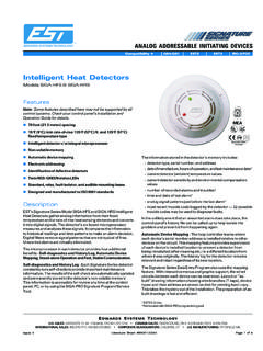
5 1. Wire the sensor base (supplied separately) per the wiring diagram, see Figure 1. Figure 2. Rotary Address Switches 2. Set the desired address on the sensor address switches, see Figure 2. NOTE: Some panels support extended addressing. In order to set the sensor above address 99 on compatible systems, carefully remove the stop on the upper rotary switch with thumb as shown in Figure 2. 3. Install the sensor into the sensor base. Push the sensor into the base while turning it clockwise to secure it in place. 4. After all sensors have been installed, apply power to the control unit and activate the communication line. 5. Test the sensor (s) as described in the TESTING section of this manual. CAUTION. Dust covers provide limited protection against airborne dust particles during shipping. Dust cov- sensor . ers must be removed before the sensors can sense smoke . Remove sensors prior to heavy COVER. remodeling or construction.
6 TAMPER-RESISTANCE. Models FSP-851, FSP-851T and FAPT-851 include a tamper-resistant capability that prevents their removal SENSING CHAMBER. COVER COVER AND SCREEN. from the bracket without the use of a tool. Refer to the base manual for details on making use of this capability. REMOVAL TABS. TESTING SENSING. Before testing, notify the proper authorities that the system is undergoing maintenance, and will CHAMBER. temporarily be out of service. Disable the system to prevent unwanted alarms. All sensors must be tested after installation and periodically thereafter. Testing methods must satisfy the Authority Having Jurisdiction (AHJ). Sensors offer maximum performance when tested and maintained in com- pliance with NFPA 72. A78-2747-03. Figure 3. N200-12-00 1 I56-1925-00R. Notifier, 12 Clintonville Rd, Northford, CT 06472, (203) 484-7161. The sensor can be tested in the following ways: A. Functional: Magnet Test (P/N M02-04-01 or M02-09-00).
7 This sensor can be functionally tested with a test magnet. The test magnet electronically simulates smoke in the sensing chamber, testing the sensor elec- tronics and connections to the control panel. 1. Hold the test magnet in the magnet test area as shown in Figure 3. 2. The sensor should alarm the panel. Two LEDs on the sensor are controlled by the panel to indicate sensor status. Coded signals, transmitted from the panel, can cause the LEDs to blink, latch on, or latch off. Refer to the control panel technical documentation for sensor LED status operation and expected delay to alarm. B. smoke Entry: Aerosol Generator (Gemini 501). The GEMINI model 501 aerosol generator can be used for smoke entry testing. Set the generator to represent 4%/ft to 5%/ft obscuration as described in the GEMINI 501 manual. Using the bowl shaped applicator, apply aerosol until the panel alarms. For FAPT-851 , smoke entry testing should be performed immediately following the magnet test.
8 Magnet test initiates an approximately 10 minute period when the detector's signal processing software routines are not active. Failure to first perform the magnet test will introduce a time delay before the detector alarms. C. Direct Heat Method (Hair dryer of 1000-1500 watts). FSP-851T and FAPT-851 only. A hair dryer of 1000-1500 watts should be used to test the thermistors. Direct the heat toward either of the two thermistors, holding the heat source approxi- mately 12 inches from the detector in order to avoid damaging the plastic housing. The detector will reset only after it has had sufficient time to cool. Make sure both thermistors are tested individually. A sensor that fails any of these tests should be cleaned as described under CLEANING, and retested. If the sensor fails after cleaning, it must be replaced and returned for repair. When testing is complete, restore the system to normal operation and notify the proper authorities that the system is back in operation.
9 HIGH SENSITIVITY SETTING. The use of the to per foot sensitivity setting requires a 90-day test period to ensure that the detector's environment is suitable for this setting. The following steps must be followed to meet Notifier sensor . and UL requirements for this high sensitivity application: COVER. 1. Each detector intended for to per foot alarm application shall have its initial alarm setting set for obscuration per foot alarm level. The initial prealarm setting for the detector shall be set to the intended alarm setting of the system. Prealarm shall be set for nonlatching operation. 2. Detectors set at to per foot are intended for use in smoke -free, environmentally con- SENSING CHAMBER. COVER COVER AND SCREEN. trolled applications, such as computer rooms and clean rooms. In order to determine if an environ- REMOVAL TABS. ment is suitable for installation, the detectors shall be operated continuously for 90 days with all envi- ronmental factors, including temperature, humidity, air flow, occupancy, etc.
10 , similar to the intended SENSING. CHAMBER. application for these detectors. An electronic history file or printer shall be used to record all events associated with the detectors under testing. 3. At the end of 90 days, the results of the test shall be inspected by an authorized Notifier represen- tative or the end user, if trained by an authorized Notifier representative. If no alarms or prealarms are recorded for the detectors under testing, the system may be set to the tested prealarm level in A78-2747-03. the to per foot range. FSP-851. CLEANING. Before removing the detector, notify the proper authorities that the smoke detector system is undergoing maintenance and will be temporarily out of service. Disable the zone or system undergoing maintenance to prevent unwanted alarms. 1. Remove the sensor to be cleaned from the system. sensor . 2. Remove the sensor cover by pressing firmly on each of the four removal tabs that hold the COVER.