Transcription of FUEL SYSTEM—3.1L DIESEL ENGINE - GIANECRI.IT
1 fuel system DIESEL ENGINETABLE OF CONTENTS pagepageGENERAL 1 fuel DELIVERY system 2 fuel injection system 23 GENERAL INFORMATIONTABLE OF CONTENTS pagepageDESCRIPTION AND OPERATIONFUEL REQUIREMENTS SHUTDOWN AND OPERATIONFUEL SHUTDOWN SOLENOIDDESCRIPTIONThe fuel shutdown solenoid is controlled andoperated by the fuel shutdown (shut-off) solenoid is used toelectrically shut off the DIESEL fuel supply to the high-pressure fuel injection pump. The solenoid ismounted to the rear of the injection solenoid controls starting and stopping of theengine regardless of the position of the acceleratorpedal. When the ignition (key) switch is OFF, thesolenoid is shut off and fuel flow is not allowed to thefuel injection pump. When the key is placed in theON or START positions, fuel supply is allowed at theinjection REQUIREMENTS DIESELDESCRIPTIONP remium quality DIESEL fuel with a minimum Cet-ane rating of 50 or higher is system DIESEL ENGINE14 - 1 fuel DELIVERY system DIESEL ENGINETABLE OF CONTENTS pagepageDESCRIPTION AND OPERATIONFUEL DRAIN FILTER/WATER GAUGE SENDING HEATER injection SHUTDOWN system PRESSURE TANK TUBES/LINES/HOSES AND CLAMPS LOW-PRESSURE fuel FITTINGS LOWPRESSURE AND TESTINGAIR IN fuel HEATER RELAY injection PUMP INJECTOR / NEEDLE MOVEMENTSENSOR INJECTOR SHUTDOWN SOLENOID SUPPLY fuel LINE LEAK PROCEDURESAIR BLEED injection PUMP AND INSTALLATIONAIR CLEANER DRAIN FILTER/WATER HEATER injection LEVEL INJECTOR FIRING system TANK AND OPERATIONINTRODUCTIONThis fuel Delivery section will cover componentsnot controlled by the
2 PCM. For components con-trolled by the PCM, refer to the fuel injection Sys-tem DIESEL ENGINE section of this fuel heater relay, fuel heater and fuel gaugeare not operated by the PCM. These components arecontrolled by the ignition (key) switch. All other fuelsystem electrical components necessary to operatethe ENGINE are controlled or regulated by the system PRESSURE WARNINGDESCRIPTIONWARNING: HIGH PRESSURE fuel LINES DELIVERDIESEL fuel UNDER EXTREME PRESSURE FROMTHE injection PUMP TO THE fuel MAY BE AS HIGH AS 45,000 KPA (6526 PSI).USE EXTREME CAUTION WHEN INSPECTING FORHIGH PRESSURE fuel LEAKS. INSPECT FORHIGH PRESSURE fuel LEAKS WITH A SHEET OFCARDBOARD (Fig. 1). HIGH fuel INJECTIONPRESSURE CAN CAUSE PERSONAL INJURY IFCONTACT IS MADE WITH THE TANKDESCRIPTIONThe fuel tank and tank mounting used with thediesel powered ENGINE is the same as used with gas-oline powered models, although the fuel tank moduleis fuel tank contains the fuel tank module andone rollover valve.
3 Two fuel lines are routed to thefuel tank module. One line is used for fuel supply tothe fuel filter/water separator. The other is used toreturn excess fuel back to the fuel fuel tank module contains the fuel gauge elec-trical sending electric fuel pump is notused with the DIESEL - 2 fuel system DIESEL ENGINEWJFUEL TANK MODULEDESCRIPTIONAn electric fuel pump is not attached to the fueltank module for DIESEL powered engines. fuel isdrawn by the fuel injection fuel tank module is installed in the top of thefuel tank. The fuel tank module contains the follow-ing components: fuel reservoir Electric fuel gauge sending unit fuel supply line connection fuel return line connection Wire harness fuel inlet filter (Strainer) fuel GAUGE SENDING UNITDESCRIPTIONThe fuel gauge sending unit is attached to the sideof the fuel pump module.
4 The sending unit consists ofa float, an arm, and a variable resistor (track). Thetrack is used to send an electrical signal used for fuelgauge the fuel level increases, the float and arm moveup. This decreases the sending unit resistance, caus-ing the PCM to send a signal to the fuel gauge on theinstrument panel to read full. As the fuel leveldecreases, the float and arm move down. Thisincreases the sending unit resistance, causing thePCM to send a signal to the fuel gauge on the instru-ment panel to move toward FILTER/WATER SEPARATORThe fuel filter/water separator is located in theengine compartment on the left side behind the gen-erator (Fig. 2).The combination fuel filter/water separator pro-tects the fuel injection pump by helping to removewater and contaminants from the fuel . Moisture col-lects at the bottom of the filter/separator in a fuel filter/water separator assembly containsthe fuel filter, fuel heater element, and fuel information on the fuel heater, refer to FuelHeater in this to the maintenance schedules in Group 0 inthis manual for the recommended fuel filter replace-ment periodic draining of water from the bowl, referto fuel Filter/Water Separator Removal/Installationin this 1 Typical fuel Pressure Test at injection Pump1 FITTING2 HIGH PRESSURE LINE3 CARDBOARDFig.
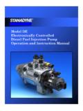
5 2 fuel Filter/Water Separator Location1 fuel FILTER/WATER SEPARATOR2 fuel FILTER/WATER SEPARATOR RETAINING NUTS3 fuel INLET HOSE4 ELECTRICAL CONNECTORS5 fuel OUTLET HOSEWJFUEL system DIESEL ENGINE14 - 3 DESCRIPTION AND OPERATION (Continued) fuel SHUTDOWN SOLENOIDDESCRIPTIONThe fuel shutdown solenoid is controlled andoperated by the fuel shutdown (shut-off) solenoid is used toelectrically shut off the DIESEL fuel supply to the high-pressure fuel injection pump. The solenoid ismounted to the rear of the injection solenoid controls starting and stopping of theengine regardless of the position of the acceleratorpedal. When the ignition (key) switch is OFF, thesolenoid is shut off and fuel flow is not allowed to thefuel injection pump. When the key is placed in theON or START positions, fuel supply is allowed at theinjection injection PUMPThe fuel injection pump is a mechanical distribu-tor type, Bosch VP36 series (Fig.)
6 3). A gear on theend of the injection pump shaft meshes with thedrive gear at the front of ENGINE . The pump ismechanically timed to the ENGINE . The ECM canmake adjustments to the timing of the injection pump contains the fuel shutdownsolenoid, fuel temperature sensor, control sleeve sen-sor, fuel quantity actuator and the fuel timing sole-noid (Fig. 3).In the electronically controlled injection pump, thepump plunger works the same as the pump plungerin a mechanically controlled injection pump, but theamount of fuel and the time the fuel is injected iscontrolled by the vehicle s ECM, instead of by amechanical governor assembly. A solenoid controlledby the ECM is used in place of the mechanical gov-ernor assembly, and it moves a control sleeve insidethe pump that regulates the amount of fuel beinginjected.
7 There is no mechanical connection betweenthe accelerator pedal and the electronically controlledinjection pump. Instead, a sensor connected to theaccelerator pedal sends a signal to the ECM that rep-resents the actual position of the accelerator ECM uses this input, along with input fromother sensors to move the control sleeve to deliverthe appropriate amount of fuel . This system is knownas Drive-By-Wire The actual time that the fuel is delivered is veryimportant to the DIESEL combustion process. The ECMmonitors outputs from the ENGINE speed sensor (fly-wheel position in degrees), and the fuel injector sen-sor (mechanical movement within the #1 cylinderfuel injector). Outputs from the Accelerator PedalPosition sensor, ENGINE speed sensor ( ENGINE rpm)and ENGINE coolant temperature sensor are also ECM will then compare its set values to theseoutputs to electrically adjust the amount of fuel tim-ing (amount of advance) within the injection is referred to as Closed Loop operation.
8 TheECM monitors fuel timing by comparing its set valueto when the injector #1 opens. If the value is greaterthan a preset value a fault will be electric fuel timing (amount of advance) isaccomplished by the fuel timing solenoid mounted tothe bottom of the injection pump (Fig. 3). fuel timingwill be adjusted by the ECM, which controls the fueltiming overflow valve is attached into the fuel returnline at the rear of the fuel injection pump (Fig. 3).This valve serves two purposes. One is to ensure thata certain amount of residual pressure is maintainedwithin the pump when the ENGINE is switched will prevent the fuel timing mechanism withinthe injection pump from returning to its zero posi-tion. The other purpose is to allow excess fuel to bereturned to the fuel tank through the fuel returnline. The pressure values within this valve are presetand can not be fuel injection pump supplies high pressurefuel of approximately 45,000 kPa (6526 psi) to eachinjector in precise metered amounts at the mechanical injection pump timing, refer toFuel injection Pump Timing in the Service Proce-dures section of this 3 fuel injection Pump1 fuel injection PUMP ASSEMBLY14 - 4 fuel system DIESEL ENGINEWJDESCRIPTION AND OPERATION (Continued) fuel INJECTORSFuel drain tubes (Fig.)
9 4) are used to route excessfuel back to the overflow valve at the rear of theinjection pump. This excess fuel is then returned tothe fuel tank through the fuel return injectors are connected to the fuel injectionpump by the high pressure fuel lines. A separateinjector is used for each of the five cylinders. Aninjector containing a sensor (Fig. 5) is used on thecylinder number one injector. This injector is calledinstrumented injector #1 or needle movement is used to tell the ECM when the #1 injector sinternal spring-loaded valve seat has been forcedopen by pressurized fuel being delivered to the cylin-der, which is at the end of its compression the instrumented injector s valve seat is forceopen, it sends a small voltage spike pulse to theECM. This tells the ECM that cylinder #1 is firing.
10 Itis not used with the other four enters the injector at the fuel inlet (top ofinjector) and is routed to the needle valve bore. Whenfuel pressure rises to approximately 15,000 15,800kPa (2175 2291 psi), the needle valve spring tensionis overcome. The needle valve rises and fuel flowsthrough the spray holes in the nozzle tip into thecombustion chamber. The pressure required to liftthe needle valve is the injector opening pressure set-ting. This is referred to as the pop-off pressure pressure in the injector circuit decreases afterinjection. The injector needle valve is immediatelyclosed by the needle valve spring and fuel flow intothe combustion chamber is stopped. Exhaust gasesare prevented from entering the injector nozzle bythe needle copper washer (gasket) is used at the base ofeach injector (Fig.)