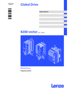
Transcription of Fuller® Automated Transmissions TRIG2500
1 Installation Guide fuller Automated Transmissions TRIG2500 . October 2007. RTO-10910B-DM2. RTO-12910B-DM2. RTO-14910B-DM2. RTO-16910B-DM2. This page intentionally left blank. Table of Contents Introduction Appendix Typical System Overview (Tower Mounted) ..67. About This Publication .. 1 10-Speed Lifting Eyes and Sensor Position Suggested Tools .. 2 (RTO-XX910X-DM2) ..69. Torque Specifications ..70. Installation Requirements Vendor List ..71. 10-Speed DM2 Wiring Diagram ..73. Installation Requirements .. 3. Connector Pin Descriptions ..75. 10-Speed 5.
2 Rear Supports .. 8. Lubrication Requirements .. 9. Air Supply Requirements for 10-Speed Transmissions .. 12. Engine Retarder Requirements .. 13. Shift Console Space Requirements .. 14. Typical Tower Mount Configuration .. 15. Typical Dash Mount Configuration .. 16. Electrical Requirements Cable .. 17. Wiring Diagram OEM Responsibility .. 20. Typical Dash Mounted System .. 21. Table of Contents Typical Tower System .. 22. Transmission 23. Power 25. Typical Dash 27. Gear Display Module .. 29. Ignition Circuit Detail .. 31. J-1587 Diagnostic Detail.
3 32. Dimmer Control Input Connection .. 34. Typical Start Enable Circuit .. 35. Typical Ignition Interrupt 37. J-1939 Data Link Detail .. 39. Vehicle Harness Connector for all Caterpillar Adam III Electronic Engines .. 46. Typical System with Eaton Shift Lever .. 49. Power Take-Off Countershaft Driven .. 55. Inertia brake Relocation Instructions 8 to 6 Bolt PTO Opening .. 56. Installation Procedures DM Clutch 59. Mounting Transmission to Engine .. 62. Line Inspection Line Inspection Instructions .. 63. Line 64. Dyno/Road Test .. 65. Line Inspection Form.
4 66. Introduction How to Use this Manual This Eaton publication is intended to be a reference guide for the installation of the UltraShift DM Transmission. General vehicle and transmission information is provided to cover the wide range of applications. This information benefits the OEM installer by providing the correct installation procedures to ensure the utmost in satisfactory operation and long service life. For additional transmission information, see the Suggested Tools section in the back of this manual. For specific engine information contact the engine OEM.
5 Failure to adhere to Eaton Installation Requirements may affect transmission performance and/or warranty coverage. UltraShift DM Transmissions are compatible with electronically governed engines equipped with a J-1939 data link and certified by Eaton Corporation. Transmissions installed at OEM facilities must meet and be approved by Eaton Application Engineering. Contact Eaton Application Engineering or your OEM Application Engineering department for proper Application form. All applica- tions must be submitted for approval. OEM facilities must submit a design package to Eaton Corporation OEM Engineering Support Group for approval prior to any OEM build.
6 A design package consist of the following information. Electrical Systems Wiring Schematic: This should show how the DM would interface with the vehicle. Individual Harness Drawings: This should show the construction of each harness. Harness Routings: This should show how each harness is routed in the vehicle. The locations of relays, fuses, power connec- tions, tie-downs, etc. Transmission Air Supply (if required). Transmission Cooling System (if required). Cooler size/type Cooler line routing Every effort has been made to ensure the accuracy of the information contained in this manual.
7 However, Eaton Corporation makes no warranty, either expressed or implied, based on the information provided. With each new application, engine manufac- tures should be contacted to make sure desired engines are compatible with their systems. 1. Introduction Suggested Tools Pressure Gauges 0-100 PSI Air Pressure Gauge Tool & Equipment Group/Kent-Moore SPX Corporation 1(800) 520-2584. Introduction Kent-Moore Part no. Description 5505027 Volt/Ohm Meter (Standard commercially available VOM). Eaton Corporation OEM Engineering Support Group TBD Pull to Neutral Box Tool & Equipment Group/Kent-Moore SPX Corporation 1(800) 328-6657.
8 Kent-Moore Part no. Description J-43318 Eaton Test Adapter Kit MD-100. Eaton Service Parts 1 (800) 826-HELP (1-800-826-4357). Part No. Description MD-200. Related Publications Troubleshooting Guide Eaton TRTS- Service Manual Eaton TRSM- Driver Instructions Eaton TRDR-2500. For more information call 1-800-826-4357. 2. Installation Requirements Requirements fuller UltraShift DM transmission systems installed at OEM facilities must meet the requirements and be approved using the Eaton Transmission Application Approval Form. Please contact Eaton Application Engineering or your OEM's Application depart- ment for the latest Application form.
9 1. Space Requirements - fuller UltraShift DM transmission systems require a minimum of 5 (127 mm) clearance from any high temperature device ( Exhaust Crossover Pipes, Catalytic Convertor) that generate heat at a maximum of 500 F. The systems to be avoided are the Shift Motors, Sensors, Wire Harness and Transmission Controller (see fig- ure). * If you must deviate from this distance and temperature an Eaton Approved heat shield must be used. 2. Cab Floor Access Plate - A cab floor access plate is necessary for access and removal of components from the trans- mission top.
10 Plate size must be sufficient to allow removal of the transmission Controller or the Electric Shifter. 3. Clutch Requirements - Must use Eaton DM clutch module. 4. Lubrication Requirements - Roadranger CD50 or equivalent E500 synthetic as specified in Eaton publication TCMT- 0021. 5. Electrical Wiring Requirements - It is the OEM responsibility to provide power and ground to the Transmission Con- troller from a reliable battery source. The power (+) connection must include overload protection per Federal Motor Car- rier Safety Regulations, Section Main Power and Ground must be able to carry 20 amps @ 9 volts with no more ohms from the battery source.
