Transcription of Fuller Heavy Duty Transmissions TRSM0917 - Road Ranger
1 Service ManualFuller Heavy duty TransmissionsTRSM0917 October 2007 Table of ContentsApplicationsWhy Oil Cooling .. 1 Why Operating Temperatures Rise .. 1 Lowering Oil Temperature .. 1 Applications for Oil Pumps and Coolers .. 1 Oil PumpsAuxiliary Countershaft Oil Pumps / Helical Models .. 2 Shimming Procedure .. 2 Shimming Chart - 1 .. 3 Determining Endplay / Shimming Procedure .. 4 Special Instructions .. 4 The Shimming Procedure .. 4 Final Check .. 5 Auxiliary Countershaft Oil Pumps / Spur Gear Models with Tapered Roller Bearings .. 6 Shimming Procedure .. 6 Shimming Chart - 2 .. 7 Determining Endplay / Shimming Procedure .. 8 Special Instructions.
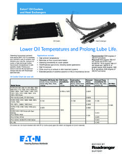
2 8 The Shimming Procedure .. 8 Final Check .. 9 Integral Oil Pump .. 10 How to Remove the Integral Oil Pump .. 10 Integral Oil Pump .. 13 How to Install the Integral Oil Pump .. 13 CoolingOil Cooler .. 16 Optimum Cooling Efficiency .. 17 LubricationProper Lubrication Procedures .. 18 Proper Oil Level .. 18 Recommended Lubricants and Maintenance Intervals .. 181 ApplicationsApplicationsWhy Oil CoolingEaton Fuller Transmissions are designed so that the inter-nal parts operate in an oil/lubricant circulating bath created by the motion of the gears and shafts. Transmission lubricants oxidize rapidly and loose effectiveness when transmission temperatures exceed 250 F. The installation of Eaton Fuller oil pumps and coolers will increase oil flow and oil cooling, low-ering temperatures to acceptable levels and prolonging the life of the Operating Temperatures RiseThe following conditions in any combination can cause oper-ating temperatures of over 250 : operating consistently at low speeds high ambient temperatures restricted air flow around transmission exhaust system too close to transmission high horse power operationLowering Oil TemperatureOil Pump ConfigurationsThere are two kinds of oil pumps available from Eaton Fuller to assist in transmission oil cooling, Auxiliary Coun-tershaft Oil Pumps and the Integral Oil Pump.
3 Auxiliary Oil Pumps are installed externally, in place of the rear bearing cover on the lower countershaft at the right rear of the trans-mission. Integral Oil Pumps are installed internally, in the main case or front section of the Oil PumpAfter January 1985, most Transmissions with a nominal torque capacity of 1400 lbs. ft. have been offered with an optional Integral Oil pump. In most Transmissions with a nominal torque capacity of 1500 lbs. ft. and above, the Inte-gral Oil Pump is Countershaft Oil PumpAn Auxiliary Countershaft Oil Pump is available when an Inte-gral Oil Pump cannot or has not been installed on a transmis-sion and oil cooling is CoolerOil Coolers should be used when vehicle configuration and operating temperatures endanger oil effectiveness (see Appli-cations for Oil Pumps and Coolers below).
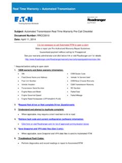
4 Oil Coolers operate at maximum cooling efficiency when mounted in a location that receives a direct flow of unheated air, for example, in front of the engine radiator. An Oil Filter can also be used, mounted in-line between the Oil Pump outlet and the Oil Cooler for Oil Pumps and CoolersOil Cooling is recommended with: engines 350 and above with overdrive Cooling is required with: engines 399 and above with overdrive transmis-sions and Gross Combined Weights (GCW's) over 90,000 lbs. engines 399 and above the 1400 lbs. ft. or greater torque capacity. engines 450 and above. vehicles operating at speeds less than 20 miles per hour or near governed RPM's for periods exceeding 30 minutes, with ambient temperatures equal or greater than 70 PumpsAuxiliary Countershaft Oil Pumps / Helical ModelsShimming ProcedureWhen shimming the Auxiliary Countershaft Oil Pump, use the appropriate Oil Pump Shims (see Shimming Chart - 1).
5 Oil Pump Shims have a smaller outside diameter than the stan-dard shims and are specially designed for use with Auxiliary Countershaft Oil Pumps. The shimming procedure can be done in the horizontal or vertical position. The procedure is the same. Shims must be aligned properly to prevent damage to the Oil Pump when final torque is DrainPlugOpeningPumpOutletCapscrewWasher Pump HousingGasket O-ringGearAssemblyIdlerCapscrewDrive PinPump AdapterGasketOil Pump ShimDrivescrewLeft-hand ThreadStrainerHose AssemblyConnectorGearAssemblyDriveValveS pringO-ringCapTee3 Oil PumpsOil PumpsShimming Chart - 1 Average the feeler gauge measurement and match the mea-surement to the feeler gauge average gap (column 1).
6 Follow the column to the right to identify the shim thickness (column 2) to be used, part number (column 3), and color code (col-umn 4) of the correct GaugeAverage Gap2 ShimThickness3 Oil Pump ShimPart - . - . - . - . - . - . - . - . - . - . - . - . - . - . - . - .05821479 Light - . - . - . - . - . - . - . - .07021687 Silver4 Oil PumpsAuxiliary Countershaft Oil Pumps / Helical ModelsDetermining Endplay / Shimming ProcedureWhen installing the Auxiliary Countershaft Oil Pump, use the existing rear bearing cover to measure the average feeler gauge gap (see Shimming Chart - 1 / column 1) and deter-mine endplay for shimming procedure as follows: Special InstructionsWhen the Auxiliary Countershaft Oil Pump is removed always install an auxiliary countershaft retaining strap with 2 - 3/8" NC X 1 and 1 - 3/8" NC X 2 - 1/2" clean capscrews to prevent the countershaft from falling.
7 Do not use an air gun tighten capscrews by hand until snug. CAUTION: Use Retaining Straps to prevent injury or damage to transmission. The Shimming the countershaft straps. an .100 gauging shim to the countershaft rear bearing shim bore, making sure that the counter-shaft rear bearing races are seated in the bearing bores. not install the countershaft rear bearing cover gasket. Position the rear bearing cover over the shim. Install two (2) clean 3/8" X 1" capscrews directly across from each other in the rear bearing cover. the capscrews to 7 lbs. in. of the output shaft six (6) times clockwise, then six (6) times counterclockwise to seat the counter-shaft bearings. Use a feeler gauge, as close to one capscrew location as possible, and measure the gap between the countershaft rear bearing cover and the auxiliary case.
8 Record the the gap as close to the 2nd capscrew loca-tion as possible and record the measurement. Aver-age the two measurements. Using the average measurement, refer to the Shimming Chart - 1 to identify the proper shim to be used in the counter-shaft PumpsOil the countershaft rear bearing covers and gauging the selected shim on the rear countershaft bearing a new gasket on the assembled oil pump mounting Install the assembled oil Apply Eaton Fuller Sealant #71205 or equivalent to the retaining Install the retaining capscrews and tighten to 35-45 lbs. ft. of CheckMake sure capscrews are properly torqued. Make sure the input shaft PumpsAuxiliary Countershaft Oil Pumps / Spur Gear Models with Tapered Roller BearingsShimming ProcedureWhen shimming the Auxiliary Countershaft Oil Pump, use the appropriate Oil Pump Shims (see Shimming Chart - 2).
9 Oil Pump Shims have a smaller outside diameter than the stan-dard shims and are specially designed for use with Auxiliary Countershaft Oil Pumps. Shimming procedure can be done in the horizontal or vertical position. The procedure is the same. Shims must be aligned properly to prevent damage to the Oil Pump when final torque is DrainPlugOpeningPumpOutletCapscrewLockwa sherPump HousingGasket O-ringGear Assembly DriveCapscrewDrivePinPumpAdapterGasketCo llarStrainerHose AssemblyConnectorGear Assembly IdlerValveSpringO-ringCapCollarCapscrewC apscrewTee7 Oil PumpsOil PumpsShimming Chart - 2 Average the feeler gauge measurement and match the mea-surement to the feeler gauge average gap (column 1).
10 Follow the column to the right to identify the shim thickness (column 2) to be used, part number (column 3), and color code (col-umn 4) of the correct GaugeAverage Gap2 ShimThickness3 Oil Pump ShimPart - . - . - . - . - . - . - . - . - . - . - . - .05821479 Light - . - . - . - . - . - . - . - . - . - .07421472+21472 Red+ - . - .07721472+21473 Red+ - . - .08021472+21474 Red+ - . - .08321472+21475 Red+ - . - .08621472+21476 Red+ - . - .08921472+21477 Red+ - . - .09221472+21478 Red+ - . - .09521472+21479 Red+Light Blue8 Oil PumpsAuxiliary Countershaft Oil Pumps / Spur Gear Models with Tapered Roller BearingsDetermining Endplay / Shimming ProcedureWhen installing the Auxiliary Countershaft Oil Pump, use the existing rear bearing cover to measure the average feeler gauge gap (see Shimming Chart - 2 / column 1) and deter-mine endplay for shimming procedure as follows: Special InstructionsWhen the Auxiliary Countershaft Oil Pump is removed always install an auxiliary countershaft retaining strap with 2 - 3/8" NC X 1 and 1 - 3/8" NC X 2 - 1/2" clean capscrews to prevent the countershaft from falling.