Transcription of Fuller Transmissions TRTS0070 - Road Ranger
1 Troubleshooting GuideFuller TransmissionsTRTS0070 October 2007 RTLO-11610 BRTLO-11610B-T2 RTLO-12610 BRTLO-12610B-T2 RTLO-12713 ARTLO-12913 ARTLO-13610 BRTLO-13610B-T2 RTLO-14610 ARTLO-14610 BRTLO-14610B-T2 RTLO-14613 BRTLO-14618 ARTLO-14713 ARTLO-14718 BRTLO-14913 ARTLO-14918 BRTLO-14918B-T2 RTLO-15610 BRTLO-15610B-T2 RTLO-16610 BRTLO-16610B-T2 RTLO-16618 ARTLO-16713 ARTLO-16713A-T2 RTLO-16718 BRTLO-16913 ARTLO-16913A-T2 RTLO-16918 BRTLO-16918B-T2 RTLO-17610 BRTLO-17610B-T2 RTLO-18610 BRTLO-18610B-T2 RTLO-18718 BRTLO-18718B-T2 RTLO-18913 ARTLO-18913A-T2 RTLO-18918 BRTLO-18918B-T2 RTLO-20913 ARTLO-20918 BRTLO-20918B-T2 RTLO-22918 BRTLOC-16909A-T2 RTLOF-11610 BRTLOF-11610B-T2 RTLOF-12610 BRTLOF-12610B-T2 RTLOF-12713 ARTLOF-12913 ARTLOF-13610 BRTLOF-13610B-T2 RTLOF-14610 BRTLOF-14610B-T2 RTLOF-14613 BRTLOF-14618 ARTLOF-14713 ARTLOF-14718 BRTLOF-14913 ARTLOF-14918 BRTLOF-14918B-T2 RTLOF-15610 BRTLOF-15610B-T2 RTLOF-16610 BRTLOF-16610B-T2 RTLOF-16618 ARTLOF-16713 ARTLOF-16713A-T2 RTLOF-16718 BRTLOF-16913 ARTLOF-16913A-T2 RTLOF-16918 BRTLOF-16918B-T2 RTLOF-17610 BRTLOF-17610B-T2 RTLOF-18610 BRTLOF-18718 BRTLOF-18913 ARTLOF-18913A-T2 RTLOF-18918 BRTLOF-18918B-T2 RTLOF-20913 ARTLOF-20918 BRTLOF-20918B-T2 RTLOF-22918 BRTLOFC-16909A-T2 General WarningsGeneral WarningsBefore starting a vehicle: in driver s shift lever in the parking brake Before working on a vehicle or leaving the cab with engine shift lever in parking wheelsDo not release the parking brake or attempt to select a gear until the air pressure is at the correct parking the vehicle or leaving the shift lever in the parking brakeDo not operate if alternator lamp is lit or if gauges indicate low (+) and (-) must be disconnected prior to any type of welding on the Tools.
2 Volt/Ohm Meter SPX / Kent-Moore 1 (800) 328-6657P/N 5505027 PC-based Service Tool Service Ranger Contact your OEM Data Link TesterEaton Service Parts 1 (800) 826-4357P/N MF-KIT-04 Shift Lever TesterEaton Service Parts 1 (800) 826-4357P/N 691795 Eaton Test Adapter KitSPX / Kent-Moore 1 (800) 328-6657P/N J- 43318 6-Pin Deutsch Dia gnostic Adapter SPX / Kent-Moore 1 (800) 328-6657P/N J-38500-60 AFor information and assistance, call the Roadranger Help Desk at 1-800-826-HELP (4357) (Mexico: 01-800 826-HELP (4357). You may also find more information about Eaton Fuller Transmissions at effort has been made to ensure the accuracy of the information contained in this manual. However, Eaton Corpo-ration makes no warranty, expressed or implied, based on the information of ContentsTable of ContentsIntroductionIntroduction .. 1-1 Diagnostic Procedure .. 1-2 Suggested Test FixuresSuggested Test Fixures .. 1-3 General ProceduresTop 2 Basic Operation and Overview.)
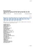
3 1-5 System Problem .. 1-8 Driving TechniquesDriving Techniques .. 1-12 Fault Code Isolation Procedure IndexFault Code Isolation Procedure Index .. 1-14 PretestPneumatic Pretest .. 2-1 Fault Code ProceduresFault Code: 62(SID: 26,40,53-56, FMI: 3,4)DDEC III - Shift Solenoid or Lockout Solenoid .. 2-4 Fault Code: 537, 536(SID: 40, 51, FMI: 11)Cummins - Shift Solenoid or Lockout Solenoid .. 2-8 Fault Code: 66,67(SID: 40,51, FMI: 5,6)Caterpillar - Shift Solenoid or Lockout Solenoid .. 2-12 Fault Code: 44,43(SID: 10,11, FMI: 3,4)MACK - Shift Solenoid or Lockout Solenoid .. 2-16 Fault Code: 62(SID: 26,40,53-56, FMI: 7)DDEC III - Mechanical System Not Responding .. 2-20 Fault Code: 544(PID: 191, FMI: 7)Cummins - Mechanical System Not Responding .. 2-26 Fault Code: 68(PID: 191, FMI:7)Caterpillar - Mechanical System Not Responding .. 2-32 FaultCode: 38(PID: S32, FMI: 7)MACK - Mechanical System Not Responding.
4 2-38 Symptom ProceduresSymptom Driven diagnostics Table ..3-1 Air Leak Test - T2 Convertible Only ..3-2 Air Leak Test - 10 Speed Leak Test - 13 and 18 Speed Only ..3-10 Splitter System Test ..3-14 AppendixService information .. A-1 Top 2 System Overview .. A-2 Splitter Cylinder Assembly - 10 Speed Only (old design) .. A-9 Splitter Cylinder Assembly - RTL-XX710 Model (latest design) .. A-11 Splitter Cylinder Assembly - RTLO-XX713 and XX718 (old design) .. A-13 Splitter Cylinder Assembly - RTLO-XX710 Model (latest design) .. A-16 Splitter Cylinder Assembly - RTLO-XX913 and XX918 (latest design) .. A-181-1 Fault Isolation ProceduresIntroductionPurpose and Scope of ManualThis manual is designed to provide detailed information necessary to perform diagnostic and troubleshooting procedures for theEaton Fuller Transmissions listed on the to Use This ManualThe key to using this manual is to follow the Diagnostic Procedure (see page 1-2) first.
5 This procedure takes you step-by-stepthrough the tests and procedures to help to diagnose the transmission ProceduresDiagnostic ProcedureDiagnostic ProcedureFollow the flowchart below for all Top 2 transmission failures. Perform tests and procedures in order as directed by the is recommended to use the MPSI Pro-Link 9000 diagnostics Tool or an approved engine manufacturers diagnostic tool to diagnose Fault active engine codes. Active transmissioncodes?NOYES Perform Electrical Pretest. Refer to the Fault Code Isolation Procedure Index to select a Fault Code Isolation Inactive Codes. Inactive Codes?NOYES Record and clear codes. Perform Pneumatic Pretest. Perform Driving Technique to reproduce the inactive fault Refer to Symptom-Driven Diag-nostics Table to select a symptom isolation procedure. Perform Pneumatic Pretest. Refer to Top 2 Basic Operation and Overview enginecodes?
6 NOYES Diagnose and repair active enginecodes per OEM recommendations. Clear active and inactive codes with MPSI scan tool. Test drive and confirm vehicle active Transmissions codes. Is Top 2 operatingproperly?NOYES1-3 Suggested Test FixuresSuggested Test FixuresNote: Only one gauge Cylinder1/8" Air Lines1. 0-100 PSI gauge2. 5/32" air line3. 5/32" push-to-connect to 1/8" NPTF4. 1/8" nipple5. 1/8" tee1. 0-100 PSI gauge2. 5/32" air line3. 5/32" push-to-connect to 1/8" NPTF4. Elbow5. 1/8" tee6. Elbow assembly7. 1/8" air line8. Grip nut9. Compression sleeve123541234567891-4 Suggested Test FixuresSuggested Test Fixures5/32" Air Lines1. 0-100 gauge2. 5/32" air line3. 5/32" push-to-connect to 1/8" NPTF4. Elbow5. 1/8" Tee6. Elbow assembly7. 5/32" air line8. Grip nut9. Compression sleeve1234567891-5 General ProceduresTop 2 Basic Operation and OverviewThe Top 2 transmission shifts like a normal 10, 13, or 18 speed transmission until the lever is put into the Auto (Top 2) Mode.
7 Thetransmission shifts automatically between the top two gears based on engine speed and the transmission is in the Auto Mode the system the transmission between the top two or decrease engine speed during a interrupts cruise control or engine brake during the shift, then the transmission through the shift pattern 7th H position for the 13/18-speed Convertible models and 8th gearfor 10-speed models. Double-clutching during lever shifts and breaking torque during button the engine has reached the shift point use the normal double-clutching procedure and move the shift lever intoAUTO : The position of the shift button does not matter when moving the lever into the AUTO position. It is recommended to leavethe shift button in the forward position so it is ready when you want to make a downshift into 7th H position for 13/18-speedmodels or 8th gear for 10-speed the engine has reached the shift point the transmission will automatically shift into high downshift from high gear into the AUTO position:Once the engine has reached the shift point the transmission will automatically downshift from AUTO sure the shift button is in the forward the engine has reached the shift point move the lever to the next lower lever position while downshifting through the shift pattern, double-clutching during lever shifts and breaking torque during ProceduresTop 2 Basic Operation and OverviewDriving Tips When the transmission is making a shift in the AUTO Mode, depressing the clutch pedal or moving the lever into theneutral position may cause the Top 2 to miss the shift.
8 To activate Top 2 Mode, the transmission must be shifted to the highest lever position when the engine has reached itsnormal shift point of at least 1400 rpm and vehicle speed is at least 40 mph. (Example: On a Super 10 the highest leverposition is 9th and 10th gears). Shifting the lever into the Auto position below 1400 rpm does not activate the AUTO Mode. If the operator moves theshift lever into the Auto lever position below the engine s normal shift point, the transmission remains in MANUAL MODE. Shift points in AUTO Mode vary depending on the following Brake HOLD Mode is available when the Top 2 Cruise option is enabled. The cruise option allows the operator to turn off theTop 2 function with the master cruise switch. When the AUTO position and Cruise Control is turned OFF, the transmissionholds in the current gear disabling auto and manual split shifts until one of the following Cruise Control is turned back lever is moved to the neutral clutch pedal is fully depressed.
9 Transmission HUNTING may occur under certain driving conditions. Raising or lowering vehicle cruise speed alleviatesthis condition. 1-7 General ProceduresDefinitionsBreak TorqueReleasing engine power or load from the transmission and drivetrain by releasing the throttle or depressing the clutch shifting technique used when moving the shift lever to the next lever position. Procedure: Depress clutch pedal, move lever to neutral, let up clutch pedal, accelerate or decelerate engine to obtain synchro-nous, depress clutch pedal again, and move lever into the shift button just prior to the starting shift. The shift button should not be moved while the shift lever is in StepAmount of change between two gear ratios expressed as a percentage. Example: The ratio step from 1st gear to 2nd gear is 35%.Shift ButtonThe button on the side of the shift knob used to change point at which the input gearing speed (engine speed) matches the output gearing speed ( road speed) and a shift can occur without PositionThe highest lever position where the Top 2 shifts between the top two gear positions, also referred to as Top 2 ModeThe transmission holds the current gear at the request of the driver by turning off the Cruise Control switch while in the AUTO ModeDriver operated splitter shifts when in the AUTO condition causing the transmission to upshift and downshift repeatedly.
10 This condition is dependent on road speed, throttle position, and engine load. 1-8 Fault Isolation ProceduresSystem Problem & Fault Code Retrieval/ ClearingSystem ProblemIf the system malfunctions, the transmission defaults to manual mode or hold mode indicating one the following faults occurred: The Top 2 Valve experienced an open or short in the circuit. The check engine light turns on and the system defaults toManual Mode. A failed component in the system prevented the splitter system from making the shift. After three (3) attempts made overa time period of about 9 seconds the system times out. The check engine light does not turn on. Shifting the transmissionto neutral or depressing the clutch obtains manual shifting mode. The Top 2 function is inactive until the vehicle isstopped and the key is turned off for at least 10 seconds. Fault Code Retrieval/ClearingThe procedure for retrieving and clearing fault codes differs between engine OEMs.