Transcription of Fundamentals of Meter Provers and Proving Methods
1 Fundamentals OF Meter Provers AND Proving . Methods . Greg Williams Flow Management Devices th 5225 South 37 Street, Suite 400. Phoenix, AZ 85040. 1. Introduction: This paper will verify the amount of time. Ed devised the double history, requirements and operation of all chronometry pulse interpolation technique Provers accepted for liquid pipeline Meter to achieve the high accuracy Meter uncertainty verification in the Liquid Oil/Gas Proving 's in a very short time period. Double Industry. It will continue with an explanation chronometry for API Meter Proving as and the industries wide acceptance of the described in API MPMS Chapter is Uni-directional Captive Displacement Prover simply a method of resolving Meter pulses (UDCDP). This document will supply the to a resolution of +/-1 part out of 10,000.
2 Reader with information regarding Meter without the need for actually counting types and the flow volumes that can be 10,000 Meter pulses during a Meter Proving . used with the UDCDP and will look at the opportunities for the use of a UDCDP as a 3. Developments Allowing Acceptance in mass prover. It will also provide the the Industry: Over the years, technological information for field verification of Provers advancements and improvements were known as a water draw. made in the design of the operating system for large bore Positive Displacement (PD). meters and Turbine meters . As well as a 2. UDCDP History: According to API, Flow greater understanding of the specifications Provers must have an uncertainty of less of the manufactured pulse output signal for than + for all measurements relating the Coriolis Mass Flow meters (CMFM's).
3 To Meter Proving including water draw and Liquid Ultrasonic Flow meters (LUFM's). uncertainty, temperature measurement meters . The advent of these changes led to uncertainty on flow Proving , pressure improvements to the ease and the ability to measurement uncertainty, etc. verify large bore meters with a UDCDP. Advancements in Meter technology along Prior to the late 1970's in order to achieve with the development of larger UDCDP, with the uncertainty of 1 part out of 10,000 using larger displacement volumes, allows the the old Prover counters with an uncertainty industry the opportunity for higher levels of of +/- 1 pulse, Provers needed a sufficient repeatability and uncertainty validation volume to gather at least 10,000 Meter significantly lower than industry accepted pulses between detectors.
4 The double error limits. The pulse interpolation chronometry technique pulse interpolation processing solution for capturing less than technique developed and patented by Ed ten thousand (10,000) total measured Francisco and precision optical switches pulses originated in the early 1980's. This and modern electronics and high speed standardized use of Double Chronometry timers eliminated the need for the extremely Pulse Interpolation (Verified in API Chapter large volumes to attain the desired 4 Section 6) inside the flow computer uncertainty. This led to the development of allowed acceptance of UDCDP for the the modern Small Volume Prover (SVP). Liquid Oil/Gas Industry. now known as the UDCDP. The double chronometry technique is a Mr. Ed Francisco, the owner of Flow simple process.
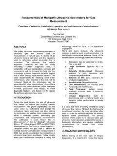
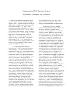
5 The time for the volume Technology Inc., in the 1960's was displaced and the time period for the whole contacted by NASA to help with Proving of Meter pulses collected during that time meters loading rocket fuel in a very short period are timed separately with high . frequency time bases. The whole Meter Figure 1: Double Chronometry Pulse Interpolation Formula and Diagrams pulses collected during that time period are multiplied by the ratio of the times to correct for differences in the time periods by the Multi-Pass Proving : Industry formula: ( Meter pulse time/Prover volume acceptance of multi-pass runs for Proving time) * number of whole Meter pulses. allows for adjustment in repeatability limits Modern computer time bases currently while still meeting uncertainty utilized in flow computers and other double helped tremendously in allowing for use of chronometry devices utilized for flow the UDCDP in large bore meters .
6 Proving use time bases at least 1 MHz Especially when using the newer frequency providing an uncertainty of far technologies like Coriolis and Ultrasonic and better than the 1 part out of 10,000 as their manufactured pulse signals. (API. required. Chapter 4, Section 8, Appendix A and Chapter 12, Section 2, Part 3 address the Pulse Interpolation Process: The first issue of multi-pass uncertainty limits.). action begins with a signal from the upstream detector switch, starting clock one The large bore Meter can now be easily (ET1, displacer elapsed travel time), next verified to an acceptable repeatability value clock two starts with the detection of the first more efficiently and faster than using a complete pulse (ET2 for the elapsed time to bidirectional pipe/ball prover.)
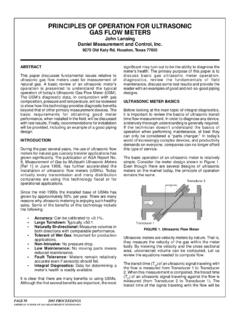
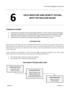
7 Allowing measure whole pulses). At the same time pipeline operators the opportunity to make the accumulation of pulses (WP, whole multiple Proving passes while increasing the Meter pulses) from the Meter being tested is limits of repeatability while still maintaining also started. the uncertainty level required in the industry. Clock one stops accumulating based on a signal from the downstream detector switch. Clock two stops accumulation based on the From API MPMS Chapter 4. detection of the first whole pulse signal from Runs at Proving repeatability to meet the downstream detector switch which also uncertainty of Meter Factor stops the whole pulse accumulation. This Proving Repeatability Meter Factor method allows for the collection of (ET1) Runs Limit Uncertainty elapsed travel time of displacer, (ET2) 3 elapsed time of whole pulse accumulation, 4 (WP) whole pulse accumulation from Meter 5 and (DV) which is the already known 6 displaced or calibrated volume for the 7 prover.
8 Taking these measurements 8 multiple times within required repeatability 9 values allows for the calculation of the new 10 K-Factor. 11 12 13 14 15 16 17 18 19 20 Table 1: Pulse Average Table from API MPMS. Chapter . month, every month the meters are left uncorrected. 4. What is a Meter prover? A Meter prover is a device used to verify It should now be clear how important Meter flow Meter uncertainty in order to establish;. Proving is to the petroleum business. the K-Factor (Pulses per unit volume) of a Meter . the Meter Factor of a Meter (factor Classification of Volumetric Proving : used with a Meter to correct To differentiate between the classifications accuracy for ambient conditions). of volumetric Meter Proving the terms static the Linearity over the calibrated flow and dynamic will be defined.
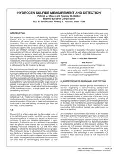
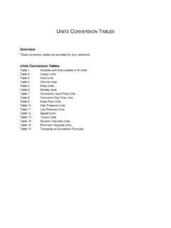
9 The difference range for the Meter . applies to the way the standard is compared the Repeatability for the Meter with the reading of the flow Meter under system. test. The Meter factor is obtained by dividing the In the static scenario the fluid is collected in prover test volume by the indicated volume a test vessel and compared to the gross of the Meter . Once the Meter factor is delivered amount of the Meter under test. determined it is used as a volume correction This is normally an open system (will be in the calculation for net standard volume of closed system when testing with a volatile a receipt or delivery of liquids. product) and will require interruption of the Actual Volume Passed thru Meter flow process to perform the Meter factor (Mfg. or Last) Meter Factor X = New Meter Factor Volume Measured by Prover Test verification.
10 Figure 2: Meter Factor Formula In the dynamic scenario the fluid remains in Why companies prove flow meters ? a closed system whereby the pulse The purpose for Meter verification or Meter registration of the Meter under test and the Proving is to provide accurate measurement pulse registration of the standard prover which then will minimize losses and used are compared directly. There is no maximize profits. The flow metering interruption of the normal flow process systems are the cash registers for all during this verification of the Meter factor. petroleum operations and this means errors in Meter factors can and will generate enormous financial errors in a company's Equipment used for Proving : invoicing in a short period of time. There are three types of measurement equipment used for verification in the Example: petroleum industry today, test measure tank If we look at the following example is Provers , volume displacement Provers , becomes clear how much money is and master meters .