Transcription of Fundamentals Of Pumps
1 Fundamentals Of Pumps Course# ME-910 Ezekiel Enterprises, LLC 301 Mission Dr. Unit 571 New Smyrna Beach, FL 32128 386-882-EZCE(3923) Ezekiel Enterprises, LLC DOE-HDBK-1018/1-93 JANUARY 1993 DOE Fundamentals HANDBOOKMECHANICAL SCIENCEV olume 1 of Department of EnergyFSC-6910 Washington, 20585 Distribution Statement A. Approved for public release; distribution is document has been reproduced directly from the best available to DOE and DOE contractors from the Office of Scientific andTechnical Information. Box 62, Oak Ridge, TN to the public from the National Technical Information Services, of Commerce, 5285 Port Royal., Springfield, VA No. DE93012178 Department of EnergyFundamentals HandbookMECHANICAL SCIENCEM odule 3 PumpsPumpsDOE-HDBK-1018/1-93 TABLE OF CONTENTSTABLE OF CONTENTSLIST OF iiLIST OF vCENTRIFUGAL 3 Impeller 3 Centrifugal Pump Classification by 4 Multi-Stage Centrifugal 6 Centrifugal Pump 10 CENTRIFUGAL PUMP 12 Net Positive Suction 12 Preventing 13 Centrifugal Pump Characteristic 14 Centrifugal Pump 15 Gas 15 Priming Centrifugal 16 POSITIVE DISPLACEMENT 18 Principle of 19 Reciprocating 19 Rotary 22 diaphragm Pumps .
2 26 Positive Displacement Pump Characteristic 27 Positive Displacement Pump 28 Rev. 0ME-03 Page iLIST OF FIGURESDOE-HDBK-1018/1-93 PumpsLIST OF FIGURESF igure 1 Centrifugal 2 Figure 2 Single and Double 2 Figure 3 Centrifugal Pump 3 Figure 4 Single Suction and Double Suction 3 Figure 5 Open, Semi-Open, and Enclosed 4 Figure 6 Radial Flow Centrifugal 5 Figure 7 Axial Flow Centrifugal 5 Figure 8 Mixed Flow Centrifugal 6 Figure 9 Multi-Stage Centrifugal 7 Figure 10 Centrifugal Pump 8 Figure 11 Centrifugal Pump Characteristic 14 Figure 12 Reciprocating Positive Displacement Pump 19 Figure 13 Single-Acting and Double-Acting 21 Figure 14 Simple Gear 22 Figure 15 Types of Gears Used In 23 Figure 16 Lobe Type Pump .. 24 Figure 17 Two-Screw, Low-Pitch, Screw Pump .. 25 Figure 18 Three-Screw, High-Pitch, Screw 25 Figure 19 Rotary Moving Vane 26 Figure 20 diaphragm 27 Figure 21 Positive Displacement Pump Characteristic 27ME-03 Rev.
3 0 Page iiPumpsDOE-HDBK-1018/1-93 LIST OF TABLESLIST OF TABLES NoneRev. 0ME-03 Page iiiREFERENCESDOE-HDBK-1018/1-93 PumpsREFERENCES Babcock & Wilcox, Steam, Its Generations and Use, Babcock & Wilcox Co. Cheremisinoff, N. P., Fluid Flow, Pumps , Pipes and Channels, Ann Arbor Science. General Physics, Heat Transfer, Thermodynamics and Fluid Flow Fundamentals , GeneralPhysics Corporation. Academic Program for Nuclear Power Plant Personnel, Volume III, Columbia, MD,General Physics Corporation, Library of Congress Card #A 326517, 1982. Stewart, Harry L., Pneumatics & Hydraulics, Theodore Audel & 0 Page ivPumpsDOE-HDBK-1018/1-93 OBJECTIVESTERMINAL references, DESCRIBE the purpose, construction, and principles of operation forcentrifugal the purposes of the following centrifugal pump a drawing of a centrifugal pump, IDENTIFY the following box wearing casing wearing the following Positive Suction Head the relationship between net positive suction head available and net positivesuction head required that is necessary to avoid three indications that a centrifugal pump may be five changes that can be made in a pump or its surrounding system that can three effects of the shape of the characteristic curve for a centrifugal how centrifugal Pumps are protected from the conditions of dead headingand pump 0ME-03 Page vOBJECTIVESDOE-HDBK-1018/1-93 PumpsTERMINAL references, DESCRIBE the purpose, construction.
4 And principle of operation forpositive displacement the difference between the flow characteristics of centrifugal and positivedisplacement a simplified drawing of a positive displacement pump, CLASSIFY the pump asone of the piston rotary rotary rotary vane the importance of viscosity as it relates to the operation of a reciprocatingpositive displacement the characteristic curve for a positive displacement the term how positive displacement Pumps are protected against 0 Page viPumpsDOE-HDBK-1018/1-93 CENTRIFUGAL PUMPSCENTRIFUGAL PUMPSC entrifugal Pumps are the most common type of Pumps found in DOE Pumps enjoy widespread application partly due to their ability tooperate over a wide range of flow rates and pump the purposes of the following centrifugal ringEO a drawing of a centrifugal pump.
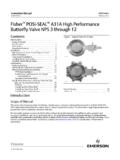
5 IDENTIFY thefollowing major box mpeller wearing casing wearing ringIntroductionCentrifugal Pumps basically consist of a stationary pump casing and an impeller mounted on arotating shaft. The pump casing provides a pressure boundary for the pump and containschannels to properly direct the suction and discharge flow. The pump casing has suction anddischarge penetrations for the main flow path of the pump and normally has small drain and ventfittings to remove gases trapped in the pump casing or to drain the pump casing for 1 is a simplified diagram of a typical centrifugal pump that shows the relative locationsof the pump suction, impeller, volute, and discharge. The pump casing guides the liquid fromthe suction connection to the center, or eye, of the impeller. The vanes of the rotating impellerimpart a radial and rotary motion to the liquid, forcing it to the outer periphery of the pumpcasing where it is collected in the outer part of the pump casing called the volute.
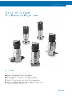
6 The voluteis a region that expands in cross-sectional area as it wraps around the pump casing. The purposeof the volute is to collect the liquid discharged from the periphery of the impeller at highvelocity and gradually cause a reduction in fluid velocity by increasing the flow area. Thisconverts the velocity head to static pressure. The fluid is then discharged from the pumpthrough the discharge connection . Rev. 0ME-03 Page 1 CENTRIFUGAL PUMPSDOE-HDBK-1018/1-93 PumpsFigure 1 Centrifugal PumpCentrifugal Pumps can also be constructed in a manner that results in two distinct volutes, eachreceiving the liquid that is discharged from a 180o region of the impeller at any given of this type are called double volute Pumps (they may also be referred to a split volutepumps). In some applications the double volute minimizes radial forces imparted to the shaft andbearings due to imbalances in the pressure around the impeller.
7 A comparison of single anddouble volute centrifugal Pumps is shown on Figure 2 Single and Double VolutesME-03 Rev. 0 Page 2 PumpsDOE-HDBK-1018/1-93 CENTRIFUGAL PUMPSD iffuserFigure 3 Centrifugal Pump DiffuserSome centrifugal Pumps containdiffusers. A diffuser is a set ofstationary vanes that surround theimpeller. The purpose of thediffuser is to increase theefficiency of the centrifugal pumpby allowing a more gradualexpansion and less turbulent areafor the liquid to reduce in diffuser vanes are designed ina manner that the liquid exiting theimpeller will encounter an ever-increasing flow area as it passesthrough the diffuser. This increasein flow area causes a reduction inflow velocity, converting kineticenergy into flow pressure. Impeller ClassificationImpellers of Pumps are classifiedFigure 4 Single-Suction and Double-Suction Impellersbased on the number of points thatthe liquid can enter the impellerand also on the amount ofwebbing between the impellerblades.
8 Impellers can be either single-suction or double-suction. Asingle-suction impeller allowsliquid to enter the center of theblades from only one direction. Adouble-suction impeller allowsliquid to enter the center of theimpeller blades from both sidessimultaneously. Figure 4 showssimplified diagrams of single anddouble-suction 0ME-03 Page 3 CENTRIFUGAL PUMPSDOE-HDBK-1018/1-93 PumpsImpellers can be open, semi-open, or enclosed. The open impeller consists only of bladesattached to a hub. The semi-open impeller is constructed with a circular plate (the web) attachedto one side of the blades. The enclosed impeller has circular plates attached to both sides of theblades. Enclosed impellers are also referred to as shrouded impellers. Figure 5 illustratesexamples of open, semi-open, and enclosed 5 Open, Semi-Open, and Enclosed ImpellersThe impeller sometimes contains balancing holes that connect the space around the hub to thesuction side of the impeller.
9 The balancing holes have a total cross-sectional area that isconsiderably greater than the cross-sectional area of the annular space between the wearing ringand the hub. The result is suction pressure on both sides of the impeller hub, which maintainsa hydraulic balance of axial Pump Classification by FlowCentrifugal Pumps can be classified based on the manner in which fluid flows through the manner in which fluid flows through the pump is determined by the design of the pumpcasing and the impeller. The three types of flow through a centrifugal pump are radial flow, axialflow, and mixed flow. Radial Flow PumpsIn a radial flow pump, the liquid enters at the center of the impeller and is directed outalong the impeller blades in a direction at right angles to the pump shaft. The impellerof a typical radial flow pump and the flow through a radial flow pump are shown inFigure 0 Page 4 PumpsDOE-HDBK-1018/1-93 CENTRIFUGAL PUMPSA xial Flow PumpsFigure 6 Radial Flow Centrifugal PumpIn an axial flow pump, the impeller pushes the liquid in a direction parallel to the pumpshaft.
10 Axial flow Pumps are sometimes called propeller Pumps because they operateessentially the same as the propeller of a boat. The impeller of a typical axial flow pumpand the flow through a radial flow pump are shown in Figure 7 Axial Flow Centrifugal PumpRev. 0ME-03 Page 5 CENTRIFUGAL PUMPSDOE-HDBK-1018/1-93 PumpsMixed Flow PumpsMixed flow Pumps borrow characteristics from both radial flow and axial flow liquid flows through the impeller of a mixed flow pump, the impeller blades push theliquid out away from the pump shaft and to the pump suction at an angle greater than90o. The impeller of a typical mixed flow pump and the flow through a mixed flowpump are shown in Figure 8 Mixed Flow Centrifugal PumpMulti-Stage Centrifugal PumpsA centrifugal pump with a single impeller that can develop a differential pressure of more than150 psid between the suction and the discharge is difficult and costly to design and more economical approach to developing high pressures with a single centrifugal pump is toinclude multiple impellers on a common shaft within the same pump casing.