Transcription of FV-SERIES VALVE - Fulflo Specialties, Co
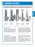
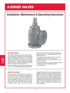
1 FV-SERIES VALVE20 APPLICATIONThe Fulflo FV series range in size from 3/8 through 2 and operate ef ficiently with liquids ofany viscosity at pressures from 2 to 1000 FV series valves are available in flange orscrew in a choice of brass, cast iron, steeland stainless used in a variety of applications, the FV series valves are ideally suited in hydraulic andlubricating systems for load regulation andsystem protection. Special trim or packings areavailable for use with fire resisting fluids andother liquids of this type. Unusual applicationsand special requirements should be referred toour engineering staff for Fulflo FV-SERIES VALVE is similar to theV- series VALVE , includes a new safer design thatprotects liquid and gasses from venting out ofthe VALVE during normal operation andadjustment conditions.
2 This VALVE has beenespecially designed to prevent the adjustingscrew from backing out while makingadjustments to the pressure setting. An o-ringhas been incorporated around the adjustingscrew to further prevent liquid from valves can be mounted in any position. Atee may be inserted in the pump discharge lineto mount the VALVE . The correct size of valveshould be installed, preferably matching thepump discharge line. Screw the VALVE into thenipple in the tee, or in the case of the flangestyle, bolt the VALVE to the companion flangescrewed into the nipple. When the VALVE is usedfor frequent bypassing of oil pressure, its outletshould be piped back to the tank. Care must betaken to have the discharge well below the oillevel in the tank to prevent air entrainment anderratic if the VALVE is used as safety or overloadrelief and operates infrequently may itsdischarge be piped back into the pump suctionline.
3 Frequent or continuous operation underthese conditions will cause excessive heating ofthe oil and possible SERIESVALVESI nstallation, Maintenance & Operating InstructionsFV- SERIESVALVESFV-SERIES21 SETTING VALVESV alves may be set with a hydraulic hand pump forcracking pressure. If a test stand is available, valveshould be connected to the discharge header with thepump bypass open, and the bypass gradually closeduntil the desired pressure registers on the VALVE adjusting screw until VALVE slightly bleedsat the set bypass pressure and lock adjusting valves are not designed to be positive shut-off,and will pass a minimal amount of leakage before theset pressure. If a VALVE is required to bypass a givenamount of fluid at a given pressure, a test standTYPICALDISASSEMBLY OF STANDARD TYPE VALVE having a flow meter in the pump discharge line mustbe available.
4 With a VALVE adjusted for crackingpressure as above, continue closing bypass until therequired flow registers on the flow meter and observepressure. Readjust pressure, if necessary, to obtaindesired pressure at desired valves provide reliable chatter-free operationwhen the system is free of abrasives and foreignmatter. Continuous filtration of the liquid used isstrongly Leaking, Dripping, Spillsor VentingThe Fulflo FV-SERIES VALVE includes a new saferdesign that prevents liquid and gasses from ventingout of the VALVE during normal operation andadjustment conditions. This VALVE has been especiallydesigned to prevent the adjusting screw from backingout while making adjustments to the pressure o-ring has been incorporated around the adjustingscrew to further prevent liquid from Efficientlyand EffectivelyThe FV-SERIES valves can be mounted in anyposition with sizes ranging from 3/8 through 2 , andwill operate ef ficiently with any application or viscosityat pressures from 2 to 1000 psi.
5 Flange or screwconnections are available in brass, cast iron, steel orstainless steel. All parts are completelyinterchangeable and convertible with other Fulflo V- series VALVE AdvantagesThese valves of fer Fulflo s patented chatter-free performance and are ideally suited for hydraulic andlubricating system protection. All Fulflo valves includea patented modulating piston design with absolute ordifferential pressure operation. Our advancedmodulating operation allows Fulflo valves to be usedin many dif ferent applications including positivedisplacement or centrifugal pump and systemprotection. Fulflo valves can be mounted in dismantle VALVE for inspection cap B O-Ring D lock nut E adjusting screw C bonnet I spring G piston F stop ring H (Not Recommended)(Special tooling is required to install new stop ring.)
6 Inspect VALVE bore and piston for wear and broken or damaged parts. Clean all partsthoroughly and re-assemble by reversing the SERIESVALVESFV-SERIES22 ASSEMBLY NUMBER IDENTIFICATION CHARTS ymbol ironBrassSteelStainless Steel (300 series Stainless)3 ConnectionsNoneFScrew ConnectionsFlange Connections 300# Flange Class Standard (250# Flange Class - Cast Iron Standard)4 Size-2-3-4-5-6-7-83/8 1/2 3/4 1 11/4 11/2 2 5,6,7 ASAF langeRatingNone-150-600300# Flange Standard (no designation required)8 FlangeStyle150# & 600#onlyABCDR aised Face, Staggered Bolt CentersSmooth Face, Staggered Bolt CentersRaised Face, Bolts on VALVE CenterlineSmooth Face, Bolts on VALVE Centerlne9O-RingMaterialRRVRSRAEPRRNBuna (Standard)Viton SiliconeAflasEthylene PropyleneNeoprene(Note.)
7 No Teflon O-Rings may be used)10 PistonMaterial/HS/SS/3 SSHardened Steel416 Stainless Steel303 Stainless Steel (For Stainless valves Only)11 Spring/AS/US/WS/XS/YS/ZSDesired Set PressuregnitteS21 EXAMPLES:FVJ-5RV/HS/WSFVS eriesJCast Iron-51 RVViton O- Piston/WSWS SpringFVJF-5R/HS/WSFVS eriesJCast IronFFlanged-51 RBuna O- Piston/WSWS SpringFVJF-5-150AR/HS/WSFVS eriesJCast IronFFlanged-51 -150 RatingAStyleRBuna O- Piston/WSWS SpringSTANDARD PRESSURE RANGE CHARTSPRING PRESSURE AND IDENTIFICATION 1/2 3/4 1 11/4 11/2 2 1 11/4 11/2 2 Low3333333 High10101010101010 Low7777777 High35353535353535 Low30303030303030 High100100100100100100100 Low60606060606060 High175175175175175175175 Low150150150150150150150 High350350350350350350350 Low300300300300300300250 High500500500500500500600 Low400400 High600600 Low550550 High750750FV- SERIESVALVESFV -SERIES23 PARTS LISTV alveSizeDIMENSIONS IN INCHESAABBCC3/8 1/2 3/4 1 11/4 11/2 2
8 531/3273/3275/1691/32101/161215/32133/41 3/8111/16115/1629/3229/16211/16313/817/1 6113/1629/3229/16211/16313/817/16111/162 1/1621/227/831 SIZE3/8 1/2 3/4 1 11/4 11/2 2 ABCDEFGHIJBODYCAPADJUSTINGSCREWO-RING (2 REQUIRED)LOCK NUTPISTON SPRING STOPRINGBONNETO-RING (1 REQUIRED)FVJFVBFVSFVSSFVJFVBFVSFVSSFVJFV BFVSFVSSFVJFVBFVSFVSSFVJFVBFVSFVSSHARDEN ED STEEL416 STAINLESS STEEL303 STAINLESS STEELALLMODELSFVJFVBFVSFVSSFVJFVBFVSFVSS FVJFVBFVSFVSS200200-B200-S200-SS201-SR20 1-BR201-SR201-SSR202-S8202-B8202-S8202-S S8204-*204-*204-*204-*205-S205-S205-S205 -SS206206-A206-SS207-**208-S208-B208-S20 8-SS223-S4223-B4223-S4223-SS47058-*7058- *7058-*7058-*300300-B300-S300-SS301-SR30 1-BR301-SR301-SSR302-S8302-B8302-S8302-S S8304-*304-*304-*304-*305-S305-S305-S305 -SS306306-A306-SS307-**308-S308-B308-S30 8-SS323-S4323-B4323-S4323-SS47006-*7006* 7006-*7006-*400400-B400-S400-SS401-R401- BR401-SR401-SSR402-S8402-B8402-S8402-SS8 404-*404-*404-*404-*305-S305-S305-S305-S S406406-A406-SS407-**408-S408-B408-S408- SS423-S4423-B4423-S4423-SS47025-*7025-*7 025-*7025-*500500-B500-S500-SS501-R501-B R501-SR501-SSR502-S8502-B8502-S8502-SS85 04-*504-*504-*504-*505-S505-S505-S505-SS 506506-A506-SS507-**508-S508-B508-S508-S S523-S4523-B4523-S4523-SS47003-*7003-*70 03-*7003-*600600-B600-S600-SS601-R601-BR 601-SR601-SSR602-S8602-B8602-S8602-SS860 4-*604-*604-*604-*505-S505-S505-S505-SS6 06606-A606-SS607-**608-S608-B608-S608-SS 623-S4623-B4623-S4623-SS47061-*7061-*706 1-*7061-*700700-B700-S700-SS701-R701-BR7 01-SR701-SSR702-S8702-B8702-S8702-SS8704 -*704-*704-*704-*505-S505-S505-S505-SS70 6706-A706-SS707-**708-S708-B708-S708-SS7 23-S4723-B4723-S4723-SS47062-*7062-*7062 -*7062-*800800-B800-S800-SS801-R801-BR80 1-SR801-SSR802-S8802-B8802-S8802-SS8804- *804-*804-*804-*505-S505-S505-S505-SS806 806-A806-SS807-**808-S808-B808-S808-SS82 3-S4823-B4823-S4823-SS4504-*504-*504-*50 4-** See o-ring selection chart** See spring pressure chartRecommended spare partsFVJCast IronFVBB rassFVSS teelFVSSS tainless SteelDIMENSIONSDD SIZEPIPE SIZEBBAA REFFV- SERIESVALVESFV -SERIES24 FVJFCast IronFVBFB rassFVSFS teelFVSSFS tainless SteelPARTS SIZE1 11/4 11/2 2 ABCDEFGHIJBODYCAPADJUSTINGSCREWO-RING (2 REQUIRED)LOCK NUTPISTON SPRING STOPRINGBONNETO-RING (1 REQUIRED)FVJFFVBFFVSFFVSSFFVJFFVBFFVSFFV SSFFVJFFVBFFVSFFVSSFFVJFFVBFFVSFFVSSFFVJ FFVBFFVSFFVSSFHARDENED STEEL416 STAINLESS STEEL303 STAINLESS STEELALLMODELSFVJFFVBFFVSFFVSSFFVJFFVBFF VSFFVSSFFVJFFVBFFVSFFVSSF500-F500-BF500- SF500-SSF501-R501-BR501-SR501-SSR502-S85 02-B8502-S8502-SS8504-*504-*504-*504-*50 5-S505-S505-S505-SS506506-A506-SS507-**5 08-S508-B508-S508-SS523-S4523-B4523-S452 3-SS47003-*7003-*7003-*7003-*600-F600-BF 600-SF600-SSF601-R601-BR601-SR601-SSR602 -S8602-B8602-S8602-SS8604-*604-*604-*604 -*505-S505-S505-S505-SS606606-A606-SS607 -**608-S608-B608-S608-SS623-S4623-B4623- S4623-SS47061-*7061-*7061-*7061-*700-F70 0-BF700-SF700-SSF701-R701-BR701-SR701-SS R702-S8702-B8702-S8702-SS8704-*704-*704- *704-*505-S505-S505-S505-SS706706-A706-S S707-**708-S708-B708-S708-SS723-S4723-B4 723-S4723-SS47062-*7062-*7062-*7062-*800 -F800-BF800-SF800-SSF801-R801-BR801-SR80 1-SSR802-S8802-B8802-S8802-SS8804-*804-* 804-*804-*505-S505-S505-S505-SS806806-A8 06-SS807-**808-S808-B808-S808-SS823-S482 3-B4823-S4823-SS4504-*504-*504-*504-** See o-ring selection chart** See spring pressure chartRecommended spare partsDIMENSIONS IN INCHESV alveSizeAABB1 11/4 11/2 2 105/16 1113/16 125/8 155/16 31/2 33/4 41/16 49/16 FOR 2 VALVE ONLYBBFULFLO- - - - -- - - - -- - - - -- - - - -BBAA REFDIMENSIONSNote: Dimensions reflect150# and 300# BBAA REFBBCEDIFBJGHAFV- SERIESVALVESFV -SERIES25 All VALVE tests 110 F.
9 To 120 F. Oil Viscosity 150 at 100 F.(Charts good from 30 to 500 )USASRSTSZSYSWSUSASZSYSXSXSWSUSASRSTSZSY S3/8 VALVE TESTS1/2 VALVE TESTS3/4 VALVE TESTSPRESSURE RANGE IN Capacity5 RANGE IN Capacity16 RANGE IN 2 4 6 8 10 20 40 60 80 100 150 OVERPRESSURE IN PER MINUTE4030201510543211 2 4 6 8 10 20 40 60 80 100 150 OVERPRESSURE IN PER MINUTE25201510543211 2 4 6 8 10 20 40 60 80 100 150 OVERPRESSURE IN PER MINUTEWSUSASZSYSXSR1 VALVE TESTS60504030201086421 2 4 6 8 10 20 40 60 80 100 150 OVERPRESSURE IN PER MINUTEPRESSURE RANGE IN Capacity25 The pressure
10 Increase or accumulation above the set pressure when the VALVE is discharging SERIESVALVESFV -SERIES26 WSUSASZSZSYSXSWSASUSWSUSXSYSXSR11/4 VALVE TESTS120100806040201612841 2 4 6 8 10 20 40 60 80 100 150 OVERPRESSURE IN PER MINUTE11/2 VALVE TESTS200160120804032241681 2 4 6 8 10 20 40 60 80 100 150 OVERPRESSURE IN PER MINUTE2 VALVE TESTS20015010050403020101 2 4 6 8 10 20 40 60 80 100 150 OVERPRESSURE IN PER MINUTEAll VALVE tests 110 F. to 120 F. Oil Viscosity 150 at 100 F.(Charts good from 30 to 500 )PRESSURE RANGE IN Capacity50 RANGE IN Capacity150 RANGE