Transcription of Galaxy 2 Series - S.D.S. Security
1 Galaxy 2 SeriesInstallation and Programming ManualHoneywell SecurityGalaxy 2 Series Installation/Programming ManualiTable of ContentsContentsSECTION 1: 1 Optional Peripherals .. 3RF .. 3 Dialler .. 3 SMS Text Messaging .. 3 Access Door Control .. 3 Remote 3 SECTION 2: QUICK GUIDE .. 5 How to Boot up .. 5 Default 5 Menu Access Operation/Navigation .. 5 How to get in and out of Engineer Mode .. 5 How to 5 How to Restore an Alarm .. 6 SECTION 3: SYSTEM 7 SECTION 4: SYSTEM WIRING .. 8 General Information .. 8 Mains Cable Type .. 8 Zone and Data Cable Type .. 9 Mains Supply Connection .. 9 Equipment Electrical 10 Galaxy 2 Series Installation/Programming ManualiiTable of ContentsConnecting the Galaxy 2 Series to the PSTN .. 11 Private Branch Exchange (PBX) Approval .. 11 REN and SEN Numbers .. 12 SECTION 5: HARDWARE .. 13 PCB Layout (2 44+).. 13 PCB Layout (2 20).
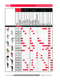
2 15 Zone 15 Wiring 16 Wiring Keyswitches .. 16 Wiring Push-Set Buttons .. 16 Zone 17 Zone Numbering System .. 18 Trig 19 Data 19RS485 Wiring Configurations .. 19RS485 Wiring 20 ECP Bus (2 44+ Only) .. 21 Built-in Dialler/Modem .. 21 LED S .. 21 Audio Header (2 44+ Only) .. 21 GSM Interface (2 44+ Only) .. 21 Panel Mounting (Plastic Box) .. 22 Installation 22 Removing the Enclosure Lid .. 22 Installing the Enclosure Lid .. 22 Removing and Replacing the Galaxy 2 Series PCB .. 22 Remove the PCB .. 23 Replace the PCB .. 23 Mounting the Plastic Enclosure Base .. 23 Fitting the Tamper Spring .. 23 Panel Mounting (Metal Box) .. 24 Installation 24 Removing and Installing the Enclosure Lid .. 24 Removing and Replacing the Galaxy 2 Series PCB .. 25 Mounting the Metal Enclosure Base .. 25 Galaxy 2 Series Installation/Programming ManualiiiTable of ContentsPeripherals - Installation, Wiring & Addressing.
3 LCD Keypad/Keyprox .. 27 Keypad/Keyprox 27 Volume Control .. 28Mk7 Keypad/Keyprox 28 Adding a Mk7 Keypad/Keyprox to the System .. 28EN50131 28 Remote Input Output (RIO) .. 29 Addressing the RIO .. 29 Connecting the RIO .. 29 Configuring the RIO .. 30 Power Supply Unit .. 31 Installation 33 Battery Test .. 33EN50131 33 ECP Zone Expander (2 44+ Only) .. 34 Zone Expander Outputs .. 34 Addressing the ECP Zone 355882H RF Receiver (2 44+ Only) .. 35 Ethernet the Ethernet Module .. 36 Ethernet 36G2 RF Portal .. 37 Mounting the Plastic Base .. 37 Attaching the PCB .. 38 Addressing the RF Portal .. 38 Connecting the RF Portal .. 39 Configuring the RF Portal .. 39 Attaching the Plastic Box Lid .. 39EN50131 396160 Keypad/Keyprox/RFH (2 44+ Only).. 40 Installation and Wiring .. 40 Addressing the 6160 Keypad .. 41 Addressing the 6160 Keyprox.
4 41 Addressing the 6160 RFH .. 41 Galaxy 2 Series Installation/Programming ManualivTable of ContentsDoor Control Module - MAX3 .. 42 Installing the MAX3 .. 42 Wiring the MAX3 .. 43 Configuring a MAX3 Reader into the System .. 44 Configuring as On-Line MAX3 .. 44 Configuring as a Stand-Alone MAX3 .. 45 Removing a MAX3 Reader from the System .. 45 Operating 462-Way Audio (2 44+ Only) .. 47 Operation of 2-Way 48 GSM Module (2 44+ Only) .. 50 SECTION 6: GENERAL OPERATION .. 51 Galaxy 2 Series Users .. 51 General Menu 51 Full Setting .. 52 Part 52 Night 53 Cancelling the Setting .. 53 Unsetting the System .. 53 Cancelling Alarms and Alerts .. 53 Alert Indication .. 53 Restoring Using Alarm Cause Code .. 54 Overriding of Faults and Tampers .. 54 Setting and Unsetting with Keyfobs .. 55 Setting and Unsetting with Keytags or Cards .. 58 Setting With MAXs.
5 58 Text 59 Additional 60 Code 60 Hot 60 Galaxy 2 Series Installation/Programming ManualvTable of ContentsSECTION 7: MENU 61 Menu 10 - Setting Options .. 61 Option 11 - Omit Zones .. 61 Option 12 - Timed Set .. 61 Option 13 - Part Set .. 61 Option 14 - Night Set .. 61 Option 15 - Chime .. 61 Menu 20 - Display Options .. 62 Option 21 - Zone 62 Option 22 - View Log .. 62 Option 23 - System Version .. 63 Option 24 - Print .. 63 Option 26 - Trace .. 63 Menu 30 - Test Options .. 64 Option 31 - Walk Test .. 64 Option 32 - Output Test .. 64 Menu 40 - Modify Options .. 65 Option 41 - Time/Date .. 65 Option 42 - Users .. 65 Adding Keyfobs (ECP) .. 68 Adding Keyfobs (RS485) .. 68 Removing Keyfobs .. 68 Adding Keytags or Cards - Mk7 485 Keyprox only .. 69 Adding Keytags or Cards - 6160 Keyprox only .. 69 Removing Keytags or Cards - Mk7 485 Keyprox/MAX3 only .. 69 Removing Keytags or Cards - ECP 6160 Tags only.
6 69 Option 44 - Mobile Nos .. 70 Option 47 - Remote 70 Option 48 - Level 3 71 Menu 50 - Engineer 1 Options .. 72 Option 51 - Parameters .. 72 Option 52 - Zones .. 85 Option 53 - Outputs .. 91 Option 56 - Comms .. 95 Option 57 - System Print .. 117 Option 58 - Keypad 118 Menu 60 - Engineer 2 Options .. 119 Option 61 - 119 Option 62 - Full Test .. 120 Option 63 - Options .. 121 SECTION 8: RF HINTS AND TIPS .. 125 How to Install RF .. 125RF Zones .. 125RF Stop Set .. 125RF 2 Series Installation/Programming ManualviTable of ContentsSECTION 9: FINAL 126 Final system Test .. 126 User 10: REMOTE SERVICING .. 127 Telephone Line 127 Direct Wire Set-Up .. 127 Remote 127 SECTION 11: FLASH UPGRADE .. 128 SECTION 12: PRINTER CONNECTION .. 129 SECTION 13: BELL-BOX CONNECTIONS .. 130 SECTION 14: EVENT LOG LIST .. 131 SECTION 15: SPECIFICATIONS .. 134 SECTION 16: COMPLIANCE AND APPROVALS.
7 136EN50131 136 Public Switched Telephone Network (PSTN) Approval .. 136 HONEYWELL Security LIMITED WARRANTY .. 137 Appendix A: Point ID Comms Triggers .. A-11 Galaxy 2 Series Installation/Programming ManualSECTION 1: INTRODUCTIONThe Galaxy 2 Series is a 12-zone intruder alarm control panel. There are 2 variants. The 2-44+ is the fullfunction version which is expandable to 44 zones. The 2-20 is an entry level version which is expandable to20 zones. This manual covers both versions. However, certain features are not available on the 2-20 following table gives the general specification for both 1. General SpecificationsThe Galaxy 2 Series requires at least one external keypad for programming and general operation. There aretwo main types of keypad Mk7 LCD Keypad: This keypad has a 2 x 16 character display and operates on the RS485 databus. Optionally, a keyprox version is available. This is a standard Mk7 keypad with a proximity card readerbuilt in to the lower right-hand corner.
8 The keyprox is for set/unset Full Text Keypad: This keypad has a 2 x 16 character display and operates on the ECP data versions are available with built-in prox reader and wireless Feature Galaxy 2-20 Galaxy 2-44+ Zones 12 expandable to 20 12 expandable 44 Outputs 4+8 expandable to 16 4+8 expandable to 28 Databuses RS485 Only RS485 and ECP PSU 1A ( @ Grade 2) (1A @ Grade 2) Alphanumeric LCD Keypads/ Alphanumeric LCD KeyProx 4 4 RIO (8 zones/4 outputs) 1 4 RF Receiver 2 2 User Codes (PIN and Card) 23 23 Groups 3+1 common group 3+1 common group Part Set 2 Part Sets 2 Part Sets Silent Night Set Yes Yes Zone Types 21 21 O/P Types 26 26 Event Log 384 384 Multi-Users 4 4 Printer Module Optional Optional PSTN Communicator/Modem On-Board On-Board GSM Comunicator/Modem - Plug on Option Ethernet Optional Optional MAX3 Optional Optional Serial Port 1 on-board 1 on-board 2-way Voice - Optional 2 Galaxy 2
9 Series Installation/Programming ManualIntroduction (cont d)Optional Peripherals Zone Expander: This gives eight extra hardwire zones and four programmable outputs. Alternativelyfour extra hardwire zones and no outputs. Ethernet Module: This optional peripheral can be connected to the RS485 line of the control panel toprovide alarm signalling, remote servicing and integrated facilities over Ethernet Local Area Network(LAN) or a Wide Area Network (WAN). MAX3: The MAX3 is a proximity reader access control device for a single door, which can also beused for setting and unsetting of the alarm control panel. RF Radio Receiver: This allows the control panel to receive signals from wire-free detectors andradio keyfobs. One radio receiver will allow the panel to assign wire-free detectors to any or all of the44 detection zones. However, two receivers can be used to increase coverage. Proximity Card Reader: This allows users to set/unset simply by presenting a card or tag in front ofthe reader.
10 The proximity card readers are built into the housing of the keypads. RIO/ PSU Control: Up to four RIO s or PSU s can be added to the RS485 Bus. Each RIO/ PSUC ontrol expands the system by eight zones and four outputs. GSM Module: This module provides mobile telecommunications between the panel and the AlarmReceiving Center (ARC).3 Galaxy 2 Series Installation/Programming ManualFeaturesRFThe system operates with the 5800 receivers on ECP and/or the RF Portal on RS485. A maximum of two RFreceivers can be fitted to the system (two on the ECP bus, two on the RS485 bus or one on each bus), tosupport up to 44 zones. The RF receivers are in addition to the prox keypads on RS485 but in place of ECPprox functionality allows the system to be split into three individual sub-systems that can be set and unsetindependently. Additionally there is a fourth common group which will set automatically when all the othergroups in the common set map have set.