Transcription of GAS COOLING SYSTEMS FOR STEAM REFORMING PLANTS - …
1 GAS COOLING SYSTEMS . FOR STEAM REFORMING PLANTS . SCHMIDTSCHE SCHACK. 1. INTRODUCTION Growing demand for STEAM REFORMING based products for chemical and refinery SCHMIDTSCHE SCHACK is a leading and processes as well as the increasing push for highly regarded supplier of components alternative fuels is leading to a greater need and SYSTEMS for the petrochemical, chemi for STEAM REFORMING PLANTS . cal, refining & metallurgical industries. Different STEAM REFORMING processes are Decades of experience in process heat the result of a knowledge based interaction transfer for STEAM REFORMING processes between the process heat transfer and generating synthesis gas have established reaction kinetics. ARVOS technical reputation, leadership in the industry and recognition as a reliable Plant capacity, product specifications, partner.
2 Catalyst technology, feedstock characteris . tics and desired STEAM production vary in STEAM REFORMING PROCESS each individual case. This applies predominantly to the Plant reliability is ensured and produc . production of synthesis gas (CO, H2) from tion costs are minimized by optimum various feed stocks including natural gas, integration of STEAM REFORMING processes refinery off-gases, LPG or naphtha. High and waste heat recovery. value products such as hydrogen, ammonia and methanol are generated in further steps downstream of the STEAM REFORMING reactor in different catalytic processes. Fuel Feed STEAM Flue gas Temperature control Air Synthesis gas BFW. Figure 1: Typical flow diagram of a STEAM REFORMING process SCHMIDTSCHE SCHACK.
3 1. INTRODUCTION Growing demand for STEAM REFORMING based products for chemical and refinery SCHMIDTSCHE SCHACK is a leading and processes as well as the increasing push for highly regarded supplier of components alternative fuels is leading to a greater need and SYSTEMS for the petrochemical, chemi for STEAM REFORMING PLANTS . cal, refining & metallurgical industries. Different STEAM REFORMING processes are Decades of experience in process heat the result of a knowledge based interaction transfer for STEAM REFORMING processes between the process heat transfer and generating synthesis gas have established reaction kinetics. ARVOS technical reputation, leadership in the industry and recognition as a reliable Plant capacity, product specifications, partner.
4 Catalyst technology, feedstock characteris . tics and desired STEAM production vary in STEAM REFORMING PROCESS each individual case. This applies predominantly to the Plant reliability is ensured and produc . production of synthesis gas (CO, H2) from tion costs are minimized by optimum various feed stocks including natural gas, integration of STEAM REFORMING processes refinery off-gases, LPG or naphtha. High and waste heat recovery. value products such as hydrogen, ammonia and methanol are generated in further steps downstream of the STEAM REFORMING reactor in different catalytic processes. Fuel Feed STEAM Flue gas Temperature control Air Synthesis gas BFW. Figure 1: Typical flow diagram of a STEAM REFORMING process SCHMIDTSCHE SCHACK.
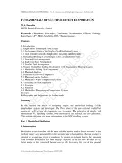
5 2 FLUE GAS CONVECTION. WASTE HEAT RECOVERY IN DOWN- STREAM STEAM REFORMER. The combustion process in a STEAM Following the direction of the waste gas reformer generates flue gas which leaves flow, the typical flow diagram shows the the reformer at about 1,000 C and is then following equipment: cooled down to temperatures below 180 C. 2-stage reformer feed superheaters, in the convection section. hairpin type Preferably the recovered heat is returned STEAM superheater, hairpin type to the STEAM REFORMING process, making the Combustion air preheater second stage, flue gas COOLING system an integral part of a tube bundle type or plate type STEAM REFORMING plant. STEAM generator, tube bundle type Combustion air preheater first stage, All process and site specific requirements tube bundle type or plate type must be taken into account and integrated in the design.
6 Depending on the process requirements an additional pre-reformer feed preheater For the material flows in the STEAM as well as a natural gas preheater made REFORMING process different types of as hairpin type can be supplied. For some heat exchangers and a wide variety of processes a boiler feed water economizer arrangements are possible. or even a process condensate preheater is Figure 2: 3D model of a convection section casing required. For specific operation modes which may result from varying load cases the convection section will be equipped with a combustion system known as duct burner enabling the flue gas to be reheated. Figure 4: One coil of a convection section Figure 3: 3D model of a waste heat recovery system Page 4.
7 SCHMIDTSCHE SCHACK. 2 FLUE GAS CONVECTION. WASTE HEAT RECOVERY IN DOWN- STREAM STEAM REFORMER. The combustion process in a STEAM Following the direction of the waste gas reformer generates flue gas which leaves flow, the typical flow diagram shows the the reformer at about 1,000 C and is then following equipment: cooled down to temperatures below 180 C. 2-stage reformer feed superheaters, in the convection section. hairpin type Preferably the recovered heat is returned STEAM superheater, hairpin type to the STEAM REFORMING process, making the Combustion air preheater second stage, flue gas COOLING system an integral part of a tube bundle type or plate type STEAM REFORMING plant. STEAM generator, tube bundle type Combustion air preheater first stage, All process and site specific requirements tube bundle type or plate type must be taken into account and integrated in the design.
8 Depending on the process requirements an additional pre-reformer feed preheater For the material flows in the STEAM as well as a natural gas preheater made REFORMING process different types of as hairpin type can be supplied. For some heat exchangers and a wide variety of processes a boiler feed water economizer arrangements are possible. or even a process condensate preheater is Figure 2: 3D model of a convection section casing required. For specific operation modes which may result from varying load cases the convection section will be equipped with a combustion system known as duct burner enabling the flue gas to be reheated. Figure 4: One coil of a convection section Figure 3: 3D model of a waste heat recovery system Page 4.
9 SCHMIDTSCHE SCHACK. 2 FLUE GAS CONVECTION. SCHMIDTSCHE SCHACK'S EXPERIENCE SCHMIDTSCHE SCHACK'S. DESIGN CONCEPTS. SCHMIDTSCHE SCHACK designs and fabri Excellence in fabrication is achieved by cates convection sections custom-made to SCHMIDTSCHE SCHACK'S decade long SCHMIDTSCHE SCHACK offers two meet specific process requirements ideally. experience in fabrication skills and quality basic design concepts. assurance. SCHMIDTSCHE SCHACK experts with Boiler derived designs usually use small diameter tubes. The tubes are horizontally extensive knowledge in process design, This specialized facility also enables easy tube diameters. The tubes hang vertically arranged, guided and held in place in a stress analysis, static calculation and transportation on waterways to sea ports.
10 In a horizontal casing allowing for free horizontal casing. In this design the tubes project management expertise assure the thermal expansion downwards. These expand thermally in horizontal direction. SCHMIDTSCHE SCHACK is certified to reliability, integrity and long life of the convection sections consist of prefabri . fabricate the pressure parts of the equipment. cated modules with casing, refractory lin A special SCHMIDTSCHE SCHACK design is a convection section in accordance with all ing and heating surfaces hence erection vertical convection section, where the flue Through the years of experience and close main international codes and regulations. time and cost are minimized. For special gas duct is built as a w ater-cooled membrane working relationship with its clients, Air preheaters of tubular or plate-type heat applications the refractory lined casing wall construction.