Transcription of Gas-Fired Vented Room Heater - Cozy heaters
1 INSTALLATION ANDOPERATING INSTRUCTIONSP/N 80900 - REV. 06/2015 NATURAL GAS VC201B-D VC351B-D VC501B-D VC701B-D VCR351B-D VCR501B-D VCR701B-D PROPANE GAS VC202B-D VC352B-D VC502B-D VC702B-D VCR352B-D VCR502B-D VCR702B-DThis appliance is equipped with a safety control system designed to protect againstimproper venting of combustion UNIT IS NOT TO BE INSTALLED IN MOBILE unit is for residential use only and is not approved for installation in mobile homes, green-houses, or environments involving dusty, wet, corrosive, or explosive conditions. Such conditionswill invalidate the warranty and may create unsafe : Operation of this Heater when not connected to a properly installed and maintainedventing system or tampering with the vent safety shut-off system can result in Carbon Monoxide(CO) poisoning and possible , maintenance, service, troubleshooting and repairs must be performed by a qualified service HOMEOWNER, DO NOT attempt any of these procedures yourself as this could expose you toproperty damage, personal injury, or loss of life and will invalidate all : Leave this manual with the : Retain this manual for future coating selected to provide longer life tothe heat exchanger may smoke slightly uponinitial firing.
2 Provide adequate ventilation ifthis WARNING: If the information in this manual is not followed exactly, a fire or explosion may result causing property damage, personal injury or not store or use gasoline or other flammable vaporsand liquids in the vicinity of this or any other TO DO IF YOU SMELL GAS: Do not try to light any appliance. Do not touch any electrical switch; do not use any phonein your building. Immediately call your gas supplier from a neighbor sphone. Follow the gas supplier s instructions. If you cannot reach your gas supplier, call the AND SERVICE MUST BEPERFORMED BY A QUALIFIED INSTALLER,SERVICE AGENCY OR THE GAS coating selected to provide longer life to the heatGas-Fired Vented Room ,4 GAS & SPECIAL PRECAUTIONS5 COMBUSTION & VENTILATION & GLASS orifice & orifice 8 PROPER BURNER 9 LIGHTING 10 TROUBLE SHOOTING ,12 BLOWER WALL STAT PRICE CAREFULLY BEFORE INSTALLING UNITT hese installation instructions are a general guide and do not supersede applicable local codes and ordinances.
3 Beforeplanning or making the installation be sure it complies with all phases of the local heating code. (Or, in the absence oflocal codes, with the latest edition of National Fuel Gas Code, , or CAN1-B149).The appliance, when installed, must be electrically grounded in accordance with local codes, or in the absence of localcodes, with the latest edition of National Electrical Code ANSI/NFPA 70, or Canadian Electrical Code of the ANSI and NFPA standards referred to in these installation instructions are the ones that were applicable atthe time the design of this appliance was certified. The ANSI standards are available from the American Gas Association,1515 Wilson Blvd., Arlington, VA. NFPA standards are available from the national Fire Protection Association, 60 Batterymarch Street, Boston,Massachusetts standards are available from International Approval Services, 178 Rexdale Boulevard, Etobicoke, Ontario,Canada M9W design of this appliance was certified to comply with the latest edition of ANSI and CSA must leave these instructions with the consumer, have them complete, and return the warranty Heater SPECIFICATIONSYour room Heater comes packed in a single carton.
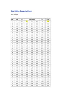
4 Before installation, check the rating plate to verify that the Model Number iscorrect and that the room Heater is equipped for the type gas you intend to OF CONTENTSTYPE CONTROL GAS MODEL NUMBERSCLOSED FRONT THERMOSTAT BULB NATURALVC201B-D VC351B-D VC501B-D VC701B-DCLOSED FRONT THERMOSTAT BULB VC352B-D VC502B-D VC702B-DRADIANT FRONT THERMOSTAT BULB NATURALN/A VCR351B-D VCR501B-D VCR701B-DRADIANT FRONT THERMOSTAT BULB VCR352B-D VCR502B-D VCR702B-DHEIGHT 20 26 26 30 WIDTH 24 30 30 36 DEPTH 15-1/4
5 15-1/4 19-1/4 19-1/4 INPUT (BTU/HR.)20,000 35,000 50,000 70,000 GAS INLET/OUTLET SIZE1/2X3/8 1/2X3/8 1/2X3/8 1/2X3/8 VENT SIZE3 4 4 5 CENTER OF VENT TO FLOOR16-1/2 21-1/2 21-1/2 25-1/2 NUMBER OF RADIANTS ( VCR SERIES)N/A 5 5 5 NUMBER OF RADIANT GLASS ( VCR SERIES) N/A 2 2 2 APPROX. SHIPPING WEIGHT ( VC SERIES)55 LBS. 84 LBS. 112 LBS. 138 SHIPPING WEIGHT ( VCR SERIES)N/A 96 LBS. 124 LBS. 150 LBS.*OPTIONAL BLOWER MODELN/A CHB-3 CHB-3 CHB-3*All 70M Btu units come with blower mounted 2 The State of Massachusetts requires that installation and service of a gas appliance be performedby a plumber or gas fitter licensed in the Commonwealth of IS A Gas-Fired , GRAVITY Vented ROOM Heater THAT WILL OPERATE SAFELY AND PROVIDE AN EFFICIENTSOURCE OF HEAT WHEN INSTALLED, OPERATED AND MAINTAINED AS RECOMMENDED IN THESE INSTALLATIONAND OPERATING INSTRUCTIONS.
6 READ THESE INSTRCTIONS THOROUGHLY BEFORE INSTALLING, SERVICING, ORUSING THIS APPLIANCE. IF YOU DO NOT UNDERSTAND ANY PART OF THESE INSTRUCTIONS, CONSULT LOCALAUTHORITIES, OTHER QUALIFIED INSTALLERS, SERVICE TECHNICIAN, THE GAS SUPPLIER, OR THE Heater must be connected to a properly installed and maintained venting system. This Heater is equipped with a manual resetvent safety shut-off device. Pilot burner outage will occur if the Heater is not connected to a vent system. Pilot burner outage mayoccur due to restriction or blockage in the vent or if connected to a masonry chimney having an area greater than the vent sizeshown on Page 2. This appliance should be Vented through a properly sized listed type B vent that has been constructed inaccordance with the National Building Code.
7 If a horizontal section of vent is used, it must slope upwards a minimum of inch perfoot of Heater must not be connected to a vent system being used for wood or coal burning appliances. The use of more than oneappliance per vent system will most likely cause the vent safety shut-off device to shut off the Heater due to the cooling of venttemperatures through the draft diverter of the second appliance. In some situations, the vent safety shut-off may shut down theheater if a large, unlined, masonry chimney is used. Due to low vent temperatures associated with more efficient heaters it may taketoo long to get the vent action going in a chimney before the shut-off device will shut down the Heater . If this is the case, werecommend lining the chimney with the proper size type B vent pipe or type B chimney : Do not bypass the vent safety shutoff switch.
8 To do so could expose the consumer toproperty damage, personal injury or possible switch, when activated, will extinguish the burner flame. If the homeowner experiences this problem, the vent system must bechecked and corrected. NOTE: An existing vent that has worked for years may not be adequate for todays design because ofhigher efficiency requirements resulting in lower stack temperatures. The following is a list of possible causes and correctiveactions. POSSIBLE CAUSES CORRECTIVE ACTION1. Blockage in vent )Check vent pipe for blockage, such as bird nest, wasp nest, twigs, leaves, ) Check that the vent cap is properly installed, not shoved too far down on the vent Burner is over firing ) Check the manifold ) Check the rate, NOTE: This appliance was orificed for elevations up to 2,000 installed at higher elevations refer to orifice chart in main burner orificesection of instructions for proper orifice size and re- orifice Improper vent system vent ) Vent too shortA)The vent should not terminate less than 5 feet above the drafthood connection.
9 A gas vent extending through an exterior wall shall not terminate adjacent to the wall or below eaves or parapets. Also, the top of the vent must be at least 2 feetabove all obstacles within a 10 feet radius, including the roof. See Figure ) Restriction in vent B)All type B vent shall extend in a generally vertical direction with offsets not system caused byexceeding 45 degrees, except that a vent system having not more than one 60 offsetsdegree offset may be allowed. Any angle greater than 45 degrees from the verticalis considered horizontal. The total horizontal run of a vent plus the horizontal ventconnector shall be not greater than 75 percent of the vertical height of the offsets used should be as far above the drafthood as possible to allow theventing action to begin before any restriction is encountered.
10 C) Incorrect vent pipe C)Use listed B type vent pipe. Do not use transite or any other type of ceramicpipe for venting. Do not use single wall pipe for vent or vent Loose connections on the 4. Check the connection on both the switch and the gas valve. Tighten if 3 vent safety wiring harnessVENTING10 or Less2 than10 10 2 above anyroof surfacewithon 10 horizontallyFIGURE AFIGURE ASeal around collar & flashings Maintain1 ClearanceSupportLateralsTermination of vent must besecurely guyed or braced ifit extends more than five (5)feet above Support AssemblyVertical ventat least 5 draft hoodCONNECTING THE VENT INTO AN EXISTING CHIMNEYSAFE (See Venting )NOTE.