Transcription of GAS TURBINES AND JET ENGINES 5.1 Introduction
1 169C H A P T E R F I V EGAS TURBINES AND JET IntroductionHistory records over a century and a half of interest in and work on the gas , the history of the gas turbine as a viable energy conversion device beganwith Frank Whittle's patent award on the jet engine in 1930 and his static test of a jetengine in 1937. Shortly thereafter, in 1939, Hans von Ohain led a Germandemonstration of jet-engine-powered flight, and the Brown Boveri company intro-duced a 4-MW gas- turbine -driven electrical power system in Neuchatel, success of the gas turbine in replacing the reciprocating engine as a power plant forhigh-speed aircraft is well known. The development of the gas turbine was less rapid asa stationary power plant in competition with steam for the generation of electricity andwith the spark-ignition and diesel ENGINES in transportation and stationary , applications of gas TURBINES are now growing at a rapid pace as researchand development produces performance and reliability increases and economic benefits.
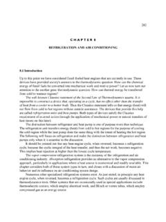
2 An Ideal Simple-Cycle Gas TurbineThe fundamental thermodynamic cycle on which gas turbine ENGINES are based is calledthe Brayton Cycle or Joule cycle. A temperature-entropy diagram for this ideal cycleand its implementation as a closed-cycle gas turbine is shown in Figure The cycleconsists of an isentropic compression of the gas from state 1 to state 2; a constantpressure heat addition to state 3; an isentropic expansion to state 4, in which work isdone; and an isobaric closure of the cycle back to state Figure (a) shows, a compressor is connected to a turbine by a rotating shaft transmits the power necessary to drive the compressor and delivers thebalance to a power-utilizing load, such as an electrical generator. The turbine is similarin concept and in many features to the steam TURBINES discusssed earlier, except that it isdesigned to extract power from a flowing hot gas rather than from water vapor.
3 It isimportant to recognize at the outset that the term " gas turbine " has a dual usage: Itdesignates both the entire engine and the device that drives the compressor and theload. It should be clear from the context which meaning is intended. The equivalentterm combustion turbine is also used occasionally, with the same the simple Rankine-cycle power plant, the gas turbine may be thought of as adevice that operates between two pressure levels, as shown in Figure (b). Thecompressor raises the pressure and temperature of the incoming gas to the levels of p2and T2. Expansion of the gas through the turbine back to the lower pressure at thispoint would be useless, because all the work produced in the expansion would berequired to drive the Instead, it is necessary to add heat and thus raise the temperature of the gas beforeexpanding it in the turbine . This is achieved in the heater by heat transfer from anexternal source that raises the gas temperature to T3, the turbine inlet of the hot gas through the turbine then delivers work in excess of thatneeded to drive the compressor.
4 The turbine work exceeds the compressor requirementbecause the enthalpy differences, and hence the temperature differences, alongisentropes connecting lines of constant pressure increase with increasing entropy (andtemperature), as the figure difference between the turbine work, Wt, and the magnitude of the compressorwork, |Wc|, is the net work of the cycle. The net work delivered at the output shaft maybe used to drive an electric generator, to power a process compressor, turn an airplanepropeller, or to provide mechanical power for some other useful the closed-cycle gas turbine , the heater is a furnace in which combustion gasesor a nuclear source transfer heat to the working fluid through thermally conducting tubes. It is sometimes useful to distinguish between internal and external combustionengines by whether combustion occurs in the working fluid or in an area separate fromthe working fluid, but in thermal contact with it.
5 The combustion-heated, closed-cyclegas turbine is an example, like the steam power plant, of an external combustionengine. This is in contrast to internal combustion ENGINES , such as automotive ENGINES ,in which combustion takes place in the working fluid confined between a cylinder and apiston, and in open-cycle gas TURBINES . Analysis of the Ideal CycleThe Air Standard cycle analysis is used here to review analytical techniques and toprovide quantitative insights into the performance of an ideal-cycle engine. AirStandard cycle analysis treats the working fluid as a calorically perfect gas, that is, aperfect gas with constant specific heats evaluated at room temperature. In Air Standardcycle analysis the heat capacities used are those for gas turbine cycle is usually defined in terms of the compressor inlet pressure andtemperature, p1 and T1, the compressor pressure ratio, r = p2/p1, and the turbine inlettemperature, T3, where the subscripts correspond to states identified in Figure Starting with the compressor, its exit pressure is determined as the product of p1 andthe compressor pressure ratio.
6 The compressor exit temperature may then be deter-mined by the familiar relation for an isentropic process in an ideal gas, Equation ( ): T2 = T1( p2 /p1)(k 1)/k[R | K]( )For the two isobaric processes, p2 = p3 and p4 = p1. Thus the turbine pressure ratio,p3/p4, is equal to the compressor pressure ratio, r = p2 /p1. With the turbine inlettemperature T3 known, the turbine discharge temperature can be determined from T4 = T3/( p2/p1)(k 1)/k[R | K]( )172and the temperatures and pressures are then known at all the significant , taking a control volume around the compressor, we determine the shaftwork required by the compressor, wc, assuming negligible heat losses, by applying thesteady-flow energy equation:0 = h2 h1 + wc orwc = h1 h2 = cp( T1 T2)[Btu/lbm | kJ/kg]( )Similarly, for the turbine , the turbine work produced iswt = h3 - h4 = cp ( T3 T4)[Btu/lbm | kJ/kg]( ) The net work is thenwn = wt + wc = cp ( T3 T4 + T1 T2)[Btu/lbm | kJ/kg]( )Now taking the control volume about the heater, we find that the heat addition perunit mass isqa = h3 h2 = cp ( T3 T2)[Btu/lbm | kJ/kg]( )The cycle thermal efficiency is the ratio of the net work to the heat supplied to theheater:0th = wn /qa[dl]( ) which by substitution of Equations ( ), ( ), ( ), and ( ) may be simplified to0th = 1 ( p2/p1) (k 1)/k[dl]( )It is evident from Equation ( ) that increasing the compressor pressure ratio increasesthermal parameter of great importance to the gas turbine is the work ratio, wt /|wc|.
7 This parameter should be as large as possible, because a large amount of the powerdelivered by the turbine is required to drive the compressor, and because the engine network depends on the excess of the turbine work over the compressor work. A littlealgebra will show that the work ratio wt /|wc| can be written as:wt /|wc| = (T3 /T1) / ( p2 /p1) (k 1)/k[dl]( ) 173 Note that, for the ideal cycle, the thermal efficiency and the work ratio depend on onlytwo independent parameters, the compressor pressure ratio and the ratio of the turbineand compressor inlet temperatures. It will be seen that these two design parameters areof utmost importance for all gas turbine ( ) shows that the work ratio increases in direct proportion to the ratioT3 /T1 and inversely with a power of the pressure ratio. On the other hand, Equation( ) shows that thermal efficiency increases with increased pressure ratio.
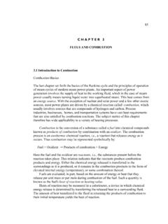
8 Thus, thedesirability of high turbine inlet temperature and the necessity of a tradeoff involvingpressure ratio is clear. Equation ( ) also suggests that increases in the ratio T3 /T1allow the compressor pressure ratio to be increased without reducing the work is indicative of the historic trend by which advances in materials allow higherturbine inlet temperatures and therefore higher compressor pressure ratios. It was shown in Chapter 1 that the area of a reversible cycle plotted on a T sdiagram gives the net work of the cycle. With this in mind, it is interesting to consider afamily of cycles in which the compressor inlet state, a, and turbine inlet temperaturesare fixed, as shown in Figure As the compressor pressure ratio pb/pa approaches 1,the cycle area and hence the net work approach 0, as suggested by the shaded cyclelabeled with single primes. At the other extreme, as the compressor pressure ratioapproaches its maximum value, the net work also approaches 0, as in the cycle denotedby double primes.
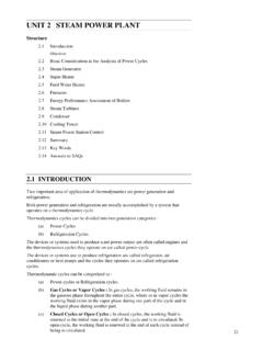
9 For intermediate pressure ratios, the net work is large and positive,indicating that there is a unique value of compressor pressure ratio that maximizes thenet work. Such information is of great significance in gas turbine design,174because it indicates the pressure ratio that yields the highest power output for giventurbomachine inlet temperatures and mass flow rate. This is an important approach tothe pressure ratio tradeoff mentioned earlier. It will be considered from an analyticviewpoint for a more realistic gas turbine model in a later section. Up to this point the discussion has focused on the closed-cycle gas turbine , anexternal combustion or nuclear-heated machine that operates with a circulating fixedmass of working fluid in a true cyclic process. In fact, the same Air Standard cycleanalysis may be applied to the open-cycle gas turbine . The open cycle operates withatmospheric air that is pressurized by the compressor and then flows into a combustionchamber, where it oxidizes a hydrocarbon fuel to produce a hot gas that drives theturbine.
10 The turbine delivers work as in the closed cycle, but the exiting combustiongases pass into the atmosphere, as they must in all combustion diagram of the cycle implementation is shown in Figure Clearly, the open-cycle gas turbine is an internal combustion engine, like the automotive engine. Notethat the diagram is consistent with Figure and all the preceding equations in thischapter. This is true because (1) the atmosphere serves as an almost infinite source andsink that may be thought of as closing the cycle, and (2) the energy released bycombustion has the same effect as the addition of external heat in raising thetemperature of the gas to the turbine inlet temperature. A cutaway of an open-cycleutility gas turbine is presented in Figure Realistic Simple-Cycle gas turbine AnalysisThe preceding analysis of the Air Standard cycle assumes perfect turbomachinery, anunachievable but meaningful ideal, and room-temperature heat capacities.