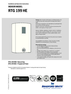
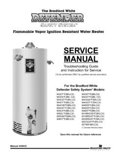
Transcription of Gas Water Heaters SERVICE MANUAL - …
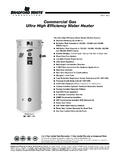
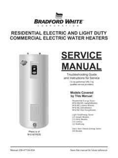
1 Save this MANUAL for future referenceManual 238-44943-00 DSERVICEMANUALT roubleshooting Guideand Instructions for ServiceFEATURING(To be performed ONLY byqualified SERVICE providers)For the Bradford WhiteDefender Safety System Models:MI30T*F(BN,CX,SX)MI30S*F(BN, CX,SX)MI303T*F(BN,CX,SX)MI40T*F(BN,CX,SX )MI403S*F(BN,CX,SX)MI404T*F(BN,CX,SX)MI5 03*F(BN,CX,SX)MI50L*F(BN,CX,SX)MI504S*F( BN,CX,SX)MI60T*F(BN,CX,SX)C(S,D)W2504T*F (BN,CX,SX)M430T*F(BN,CX,SX)M440T*F(BN, CX,SX)M4403S*F(BN,CX,SX)M4503*F(BN,CX,SX )M460T*F(BN,CX,SX)M1XR403S*F(BN,CX,SX)M1 XR504T*F(BN,CX,SX)M2XR504T*F(BN,CX,SX)M2 XR65T*F(BN,CX,SX)M2C504T*F(BN,CX,SX)50T6 5F(B*N,C*X,S*X)65T65F(B*N,C*X,S*X)(*) Denotes Warranty YearsGas Water HeatersFlammable Vapor IgnitionResistant Water HeatersThe Bradford WhiteDEFENDERS afety System Flammable Vapor Ignition Resistant Water HeatersTable of ContentsPage SERVICE ProcedureIntroduction 3- - -Trouble shooting Chart 4- - -Inner Door Gasket Removal, Inspection, Replacement and Installation 7RG-IThermocouple/Thermopile Testing and Replacement10RG-IIPilot Assembly Inspection Cleaning and Replacement13RG-IIIP iezo Igniter, Electrode Testing and Replacement 14RG-IVWhite Rodgers/Robertshaw Gas Valve Testing and Replacement15RG-VHoneywell Gas Control Testing, Disassembly, and Replacement 20RG-VIBurner Operation Inspection, Adjustment.
2 Cleaning and Replacement 31RG-VIIR esettable Thermal Switch Testing and Replacement 34RG-VIIIS creenLok Flame Arrestor Cleaning36RG-IVDip Tube and Anode Inspection and Replacement37RG-XGeneric Parts List 39- - -222 The Bradford White DEFENDER Safety System The Bradford White DEFENDER Safety System was designed to resistthe ignition of flammable vapors that can occur outside of the waterheater. Use and installation are nearly identical to previous versions ofatmospherically fired and vented Water Heaters . A number of exclusivedesign features are incorporated in the system that will require additionalknowledge on the part of the qualified SERVICE provider. The followinginformation will instruct SERVICE professionals on the function, properdiagnosis and repair of Water Heaters employing the Bradford WhiteDEFENDER Safety the Safety System WorksDuring normal operation, air for combustion is drawn into the waterheater through the opening in the jacket. This air travels down and aroundthe combustion chamber and enters through holes in the very bottom ofthe corrosion-resistant combustion chamber.
3 The air then travels upthrough the oriented flame arrestor plate louvers, where the velocity of theair is increased and its direction altered. The air then mixes in a normalmanner with the supplied gas and is efficiently combusted, producing verylow NOx the case where trace amounts of flammable vapors are present in the airflowing into the combustion chamber, the vapors are harmlessly ignitedby the burner / pilot flame. If flammable vapors are in sufficient quantityto prevent normal combustion, the burner/pilot flame is shut the flammable vapors continue to the burner, the flame arrestorplate prevents the flames from traveling backwards and igniting vaporsoutside of the combustion chamber. The calibrated, multipurpose thermalswitch recognizes this and shuts down the pilot and main burner. Thisswitch also deactivates the burner and pilot in the unlikely event ofrestricted airflow caused by severe lint, dust or oil accumulation on thearrestor Rodgers/Robertshaw Gas Valve Troubleshooting ChartSYMPTOMPROBABLE CAUSECORRECTIVE ACTIONP ilot Will Not Light1.
4 No incoming gas or too low gas Gas control knob set to wrong Pilot light button not being fully depressed when attempting to light Pilot orifice or pilot tube is obstructed or Pilot electrode not sparking to Piezo igniter not Poor thermocouple connection at combination thermostat/gas Thermocouple not fully engaged in pilot assembly Pilot flame is not fully enveloping the thermocouple hot Weak or defective Open ECO on combination thermostat/ gas Defective magnet in combination thermostat/gas Resettable thermal switch has Will Notstay litwhen button isreleasedPilot will light butthe main burnerwill not come on1. Combination thermostat/gas valve set too low for desired Water Combination thermostat/gas valve temperature is Insufficient gas supply or low gas Combination thermostat/gas valve has wide differential or is out of goes outperiodically (afterheating cycles,once a day, oncea week etc.)1. Insufficient combustion air Incorrect, clogged vent system/ vent terminal or Inconsistent gas supply or gas enough hotwater1.
5 Combination thermostat/gas valve set too low for desired Water Cold inlet Water temperature is very High demand Incorrectly sized Water heater for Combination thermostat/gas valve is out of calibration/not Out of spec dip tube is diluting hot Water with cold Turn on gas supply and/or check line Review lighting instruction. Set combination/thermostat gas valve to correct Review lighting instruction. Fully depress pilot lighting Clean, repair or Verify correct electrode position. Replace pilot Replace Piezo Check connection at combination thermostat/gas valve. Proper tightness should be finger tight plus Inspect thermocouple to ensure that it is fully engaged into pilot Adjust tip of thermocouple to be fully engulfed by pilot Check thermocouple and replace if Check ECO continuity and replace combination thermostat/gas valve if Check magnet operation and replace combination thermostat/gas valve if Determine cause of switch activation. To reset, depress button on resettable thermal switch located on inner Adjust temperature dial on combination thermostat/gas Check temperature dial setting on combination thermostat/gas Check gas supply and line Check combination thermostat/gas valve for proper operation, replace if Verify adequate combustion air is available to the unit.
6 Check and clear Jacket slot openings of any dirt, dust, restrictions or other obstructions. Inspect flame arrestor plate and clean with stiff bristled brush and/or vacuum to remove any debris Check venting for proper sizing and proper operation3. Check gas supply and line Check dial on combination thermostat/gas cold Water going into the heaterwill decrease the amount of hot waterproduced. It may be necessary to temperincoming Water Adjust high demand Contact Plumbing Check combination thermostat/gas valve for proper operation, replace if Inspect dip tube and replace if See SERVICE Procedure RG-V, Page See SERVICE Procedure RG-III, Page See SERVICE Procedure RG-III, Page See SERVICE Procedure RG-IV, Page See SERVICE Procedure RG-II, Page 85. See SERVICE Procedure RG-V, Page 146. See SERVICE Procedure RG-V, Page 132. See Installation & operation See SERVICE Procedure RG-V, Page 124. See SERVICE Procedure RG-V, Page 121. See SERVICE Procedure RG-VIII, Page 223.
7 See SERVICE Procedure RG-V, Page 125. See SERVICE Procedure RG-V, Page 126. See SERVICE Procedure RG-IX, Page 23 Flammable Vapor Ignition Resistant Water Heaters444 Honeywell Gas Control Troubleshooting ChartLED StatusControl StatusProbable CauseNone (LED not onor flashingGas Control is operating flame may not be for pilot flame through sightglass and light if set point knob is in PILOT position then pilot flame isdetected. Turn set point knob todesired flash andthree secondpauseLED oncontinuously(Solid)Set point knob has been recentlyturned to the OFF position. Waituntil LED goes out beforeattempting to relightTwo flashes andthree secondpauseWeak pilot signal detected. Systemwill reset when pilot flame Gas Control is Gas Control is not powered. Thermopile Control is powered and waitingfor the set point knob to be turned toa Water temperature point knob was turned to OFF Thermopile failure2. Unstable pilot3. Pilot tube block or Resettable thermal switch hasopenedServiceProcedureIf the pilot will not staylit replace pilotassembly.)
8 If problempersists replace thermostat todesired will go out and thecontrol will functionnormally when the pilotis See SERVICE procedure RG-II2. See SERVICE procedure RG-III3. See SERVICE procedure RG-III4. See SERVICE procedure RG-VIIIF lammable Vapor Ignition Resistant Water HeatersGreen LED IndicatorObserve green LED indicator onGas Control. Error flash codes aredisplayed with a three second pausebefore repeating. Check and repairthe system as noted in thetroubleshooting table flashes andthree secondpauseInsufficient Water heating. Systemwill Temperature sensor out ofcalibration1. See SERVICE procedure RG-VIFour flashes andthree secondpauseExcessive tank must be Temperature sensor out ofcalibration2. Faulty Gas Control1. See SERVICE procedure RG-VI2. See SERVICE procedure RG-VI555 Honeywell Gas Control Troubleshooting ChartLED StatusControl StatusProbable CauseFive flashes andthree secondpauseThermostat/well sensor Control electronic flashes andthree secondpauseEight flashes andthree secondpauseStanding pilot remains on while setpoint knob is in OFF Damage to the Temperature sensor resistanceout of Control need to be Control is wet or valve stuck in open See serviceprocedure RG-VI1.
9 Reset Gas Control2. Replace Gas Gas Vapor Ignition Resistant Water HeatersGreen LED IndicatorObserve green LED indicator onGas Control. Error flash codes aredisplayed with a three second pausebefore repeating. Check and repairthe system as noted in thetroubleshooting table leak detected by flashes andthree secondpauseExcessive amount of Water in drainpan/ Water Check T&P valve2. Check all Water Pressurize and leak test Door Removal ProcedureStep knob of the combinationthermostat/gas valve to the OFF outer jacket burner access doorStep Door ) Disconnect resettable thermal switch wire leads (leading from Gas Control/gas valve).b) Remove (2) hex drive screws from right side inner ) Remove (2) hex drive screws from flange section of inner ) Remove (2) hex drive screws from left side inner ) Remove inner door and inspect per step 4. Fully inspect inner door gaskets for the following:>Tears>Other imperfections that will inhibit proper seal>Missing Material >Gasket adhesion to inner door>Cracks>Material left on combustion chamber (around opening)>Dirt or debrisIf the gasket is not effected by any of the above, gasket replacement is not required.
10 If replacement is required,proceed toInner Door Gasket Replacement Door Gasket Replacement the information in these instructions is notfollowed exactly, a fire or explosion may result causingproperty damage, personal injury or inspection of inner door as noted in step 4, completely remove gasket and adhesive residue from rightand left side inner doors as RTV sealant (recommended bead size 1/8") to secure the inner door gasket to the inner door sections(right & left). Refer to illustration on next page for proper application. Note the overlap configuration in theflange area of the inner door. Set the flange section first, this will help to achieve the proper over lap Robertshaw Control,rotate knob clockwise tothe OFF Bradford WhiteDEFENDERS afety System For White Rodgers Control,depress knob slightly and rotateclockwise to the OFF Honeywell Control, rotateknob counter-clockwise to the OFF PROCEDURE RG-IInner Door/Gasket Removal, InspectionReplacement and ReinstallationResettable Thermal SwitchWire ConnectionHex Drive ScrewsRight and Left Side Inner Drive Screws atFlange Area of Inner Door777 Installation of Inner Door With fastener connections may allowfor seal breach of inner door.