Transcription of GE Technical Data of Phase Vacuum Recloser
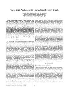
1 General Rating Structure of high voltage circuit Breakers: IEEE 1999andConsiderations for selection of circuit Breakers for Capacitive Current Switching and TRVS ummary Prepared byHimanshu BahiratMichigan Technological UniversitySpring Semester 2008 General Rating Structure of high voltage circuit Breakers :IEEE 1999GE Technical Data of Power/Vac Three Phase Vacuum RecloserConsiderations for selection of circuit Breakers for Capacitive Current SwitchingRatings for capacitance current switching1) Rated overhead line charging current;2) Rated isolated cable and isolated shunt capacitor bank switching current;3) Rated back to back cable and isolated shunt capacitor bank switching current;4) Rated transient inrush current peak;5) Rated transient inrush current frequency.
2 Considerations for selection of circuit Breakers for Capacitive Current SwitchingCapacitive currents can be encountered in following situations : Switching of no load overhead lines Switching of no load cables Switching of capacitor banks Switching of filter banksSelection of rating of circuit breakers to switch capacitive current following considerations are required: Application Power frequency of the network Grounding situations of the network Presence of single or two Phase ground faultsOverhead line charging current and Interruption No Load Overhead Lines : Uncompensated Compensated Uncompensated lines : Especially long lines are represented as charging current and Recovery voltages on interruption of charging currentsCompensated Lines.
3 Have lesser charging currents hence lesser recovery Half cycle of recovery voltageFigure Energization of no load lines: basic phenomenaCable Energization and de energizationEnergization of cables : Isolated Cable Back to Back CableThe inrush currents in cables is non Rate of Rise should not over the breaker Typical circuit for back to back switchingFigure Equivalent circuit for back to back cable switchingShunt capacitor bank energization and de energizationFigure Parallel capacitor banksEnergization of shunt capacitor banks.
4 Isolated capacitor banks Back to Back capacitor banks The inrush currents are oscillatory and have high frequenciesInitial Rate of Rise should not over the breaker voltages can be high ,especially if there are voltage and current wave shapes in the case of a restrikeTransient Recovery VoltageVoltage which appears across the circuit breaker contacts after interruption of fault or interruption of circuit .It consists of the high frequency voltage superimposed on systemfrequency voltageGenerally the resultant voltage wave turns out to be 1 cosine wave and also has the exponential Equivalent RLC circuitTransient Recovery VoltageIEEE C37 011 Application guide for Transient Recovery voltage of AC high voltage circuit breakers.
5 Specifies the TRV envelope to be used for selection of circuit on System VoltageSystem Conditions decide The circuit breaker specific TRV envelope is to be calculated and system TRV is to be compared to this system TRV should be below the circuit breaker TRV envelope to make the Equivalent RLC circuitFigure TRV envelopes 100 kV and belowFigure TRV Envelopes above 100 kV