Transcription of GENERAL SPECIFICATION FOR THE CIVIL SUB-03-017 …
1 GENERAL SPECIFICATION FOR THE CIVIL ENGINEERING AND BUILDING DESIGN and construction of secondary substations SUB-03-017 Appendix 1 10/07/2018 _____ SP Power Systems Limited APPENDIX 1: DRAWINGS The guidance drawings listed below are typical layout and construction details deemed to satisfy SPEN s functional CIVIL and building requirements for secondary substations . Constructors shall note that where provided such typical details may be generic and may not reflect exact on-site requirements on a project/site-specific basis. Where applicable and considered appropriate by SPEN, additional typical deemed to satisfy construction detail drawings may be issued on a project-specific basis. Variations or changes to the deemed to satisfy guidance drawings shall be submitted to SPEN for audit and agreement prior to any work starting on-site. Drawing No. Drawing Title Revision SP2022244 Typical 11kV GRP Plinth (No Metering) 5 SP2103445 Typical 11kV GRP Plinth (With Metering) 5 SP2142493 Typical 11kV RMU GRP Plinth (With Metering) 5 SP3020357 Typical 11kV Brick Built Substation (Close Coupled Gear) 6 SP4000542 Typical Z Vent Louvered Ventilation Unit For Brick Built Substation 5 SP4000543 Typical Hardwood Doors for 11kV substations 4 SP4000545 Typical 11kV Brick Built Substation (X or Y Type Separate Gear) 5 SP4008870 Typical 11kV Brick Built Substation (3 Panel Board With Metering) 6 SP4049060 Typical 11kV Brick Built Substation (D or G Type RMU With Metering) 10 SP4053389 Typical 11kV Brick Built Substation (Double Side by Side) 3 SP4058664 Typical 11kV Brick Built Substation (Double Square) 3 SP4102117 Typical 11kV GRP Plinth D Type RMU with MU Single Plinth 2 SP4105959 Typical 11kV Brick Built (LV Generation Substation 3 SP4132847 Typical 11kV GRP Plinth G or D Type RMU (indoor Kit))
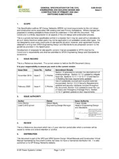
2 2 11157982152153590 ELEVATIONREAR ELEVATIONFRONT ELEVATIONPLAN3590 slabcable slots - belowto trench sides &215mm BrickworkSECTION B-BSECTION A-ATrenchCableSlot6852035== Door opening300 Slot82522538538575 CableSlotGalvanised steel ventilatorsCableSlotto top, on Visqueen or similar(anti-crack) fabric with 20mm cover concrete reinforced with A142 Floor slab to be min. 150mm thk. NOTEIt is essential that EnergyNetworkspersonnel can access& properly secure on egressFacing brick to finishDETAIL AT DOORWAY suit door detail course below cover1 sheet top, 1 sheet bottom,2 sheets of A252 fabric -to be reinforced withConcrete floor over cable slotsmin. 100mm bearingcable lintels overover open trench areato u/s to prevent movement)plywood covers (with battens fittedProvide 19mm thk. temporaryover cable slotsReinforced floor slab approved dpm, on sand blindingDETAILSEE metal lintelProprietary corrosion resistantDETAILSEE150mm thickness of rounded sand filled, trench topped with Cable trench & slots to be50150(or similar approved)with 2 layers of Visqueenlevel and smooth, topped10mm Thk.
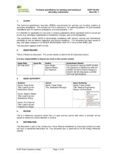
3 Cured bed joint,Scale 1:1015010036903790 Slab o/a36901003790 Slab o/aROOF SECTIONROOF PLANFOUNDATIONPLAN OF BRICKWORK BELOW FLOOR SLABC oncrete slab, reinforced withmin. A393 fabric with 40mm coverto sides, top and to be min. 400mm2501115==CL778778665665180021591090 9215215 FallFall215 CableSlotCableSlot2260 Galvd. barA252 Fabric reinft. 900 X 900mm sheetHaulageeye (seedetail)HAULGE EYE DETAIL Scale 1:20CL130100300180125 Cover150150R50100 Coverall doors at all times. Anyhardwood, metalwork or GRPconstruction doors that mayshrink, warp, wind, distort,corrode or bind will not leaf to open (min. 150mm end bearing)laps to be 400mm20mm cover to bottom,75mm cover to sides andRoof reinft. min. A393 mesh withventilator lintels over(see detail)For plant installation:Weak mix concreteor graded stone infillwith suitable polysulphideRake out and pointmovement joint sealantDripLINTOL TO VENT OPENING SCALE 1:20 Min. 2 No. 6mm dia. bars at 45mm centres(shape code 21 bar length 1040mm 'A'=940mm)100010314025mm Coverto graded stone infill is used(top to be level with )gravel chippings Additional foundation and/orground improvement worksto constructors designto suit site-specific conditions600600mm I/Dcable ductNOTEScScaleA2 SizeStatusLocationDrawnTitleDrg.
4 PowerSystems LtdSystem Design, Drawing Office3 Prenton Way , Prenton , CH43 3 ETTelephone 0151 6092491 ISSUEDSP3020357 TYPICAL TRADITIONAL BUILDING DETAILS FOR11kV BRICKBUILT SUBSTATION(CLOSE COUPLED GEAR)1 UPDATES TO REFLECT CHANGESTO CIVIL POLICY DOCUMENTSG eneralThis drawing is to be read in conjunction with document SUB-03-017 GeneralSpecification for the CIVIL Engineering and Building Design and construction ofSecondary substations . It is the constructor's responsibility to confirm, beforeconstruction, that the details on this drawing are correct as per is a generic guidance drawing that is deemed suitable for construction . Howeverthe constructor should consider all site specific risk that will affect the design andoperation of the substation. Proposed substation details are to be submitted foracceptance before shown on this drawing are typical for this type of substation building but maynot be suitable for substations housing alternative equipment. The constructor shallsatisfy themselves that the appropriate details shown are correct depending on thetype of substation being concrete shall be in accordance with the SPECIFICATION and attain the relevant cubcrushing strength at 28 E LJ ^ Foundations are to be set on undisturbed inorganic strata that provide the requiredminimum design safe ground bearing capacity.
5 Minimum bearing capacity to be E & E LJ ^ A flat, level and smooth floor surface is essential for installation of plant. Tolerancesto finished level expressed as a maximum permissible deviation beneath a straightedge with feet placed anywhere on the floor shall not exceed 1mm in 1m or 3mm in3m. Floors to be cured, prepared & painted with 2 No. Coats of non-slip floor paint W , LJ E strength and max 7% and durability designation F2 S2 (Ex Engineering BrickworkClass B) in English bond except for exposed faces. d , LJ E strength and max 12% and durability designation F1 S1 or facing brickwork to fair faced smooth textured solid concrete bricks, sized tomatch external facing bricks and with a mean compressive strength of not less than E Class iii shall be 215mm English garden wall bond or Collar jointed stretcher of collar jointed double stretcher walls to be tied together by means of type 1or type 2 stainless steel ties laid in every fourth course at 375mm centres and set back38mm from outer face, ties are to be of proposed doors shall be submitted to SPEN for comment, before GRP faced aluminium or steel security doors are the preferred option,unless stated alternative option for hardwood doors (see Drg SP4000543 for details)
6 Or GRPdoors is also Trench & SlotsOn completion of cabling, cable trench and slots to be filled with dry sand topped witha minimum 150mm depth of rounded gravel chippings (top to be level with FFL).Roof^ Z E LJ ^ Wherever practicable, roofs should be cast in situ reinforced concrete constructionwith a soffit finish. Slip joints shall be incorporated at wall bearings, polysulphidesealed externally. Internal / External faces of concrete to be fair faced. All externalfaces to be cured, prepared, primed and finished with a two coat high performance(Aliphatic) polyurethane waterproofing system (flat roof grade) with glass fibre matreinforcement to initial coat, Coat of LPL bonding primer then2No. Coats of LPL from Liquid Plastics Tel. 01772 259 781 or Equal SystemAll finishes are to be in accordance with the manufacturers permanent structural metal soffit shutters are used as part of a compositeroof system these shall be corrosion resistant and the Constructor's proposals forscreening or tagging for earthing purposes shall be expressly agreed with SPEN priorto shown is typical for a single 500kVA transformer typical ventilation indicated may not be adequate in certain supply conditionswhich might require additional or alternative ventilation Typical Deemed to Satisfy DrawingsHardwood DoorsSP4000543 Meter CupboardsSP4078901 Vent for Brickbuilt substation 250825 MIN.
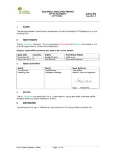
7 2410359031601123457536904150400751500150 075753590 MIN. 2502152154050215215231045721521528014002 15215 MIN. 100 MIN. 100 MIN. **150150100125R 50100100025251031402525251801003005075 NOTEScScaleA1 SizeStatusLocationDrawnDrg. PowerSystems LtdSystem Design, Drawing Office3 Prenton Way , Prenton , CH43 0151 6092491 ISSUEDSP40005451 TRADITIONAL BUILDING DETAILS FOR11kV BRICKBUILT SUBSTATION(X OR Y TYPE SEPARATE SWITCHGEAR) UPDATES TO REFLECT CHANGES TOCIVILS POLICY DOCUMENTG eneralThis drawing is to be read in conjunction with document SUB-03-017 GENERAL SPECIFICATION forthe CIVIL Engineering and Building Design and construction of secondary substations . It is theconstructor's responsibility to confirm, before construction , that the details on this drawing arecorrect as per is a generic guidance drawing that is deemed suitable for construction . However theconstructor should consider all site specific risk that will affect the design and operation of thesubstation. Proposed substation details are to be submitted for acceptance before shown on this drawing are typical for this type of substation building but may not besuitable for substations housing alternative equipment.
8 The constructor shall satisfythemselves that the appropriate details shown are correct depending on the type of substationbeing concrete shall be in accordance with the SPECIFICATION and attain the relevant cub crushingstrength at 28 E LJ ^ Foundations are to be set on undisturbed inorganic strata that provide the required minimum LJ D LJ E & E LJ ^ Floors of substations housing indoor switchgear shall have a visqueen damp proof membraneinstalled where graded stone infill is flat, level and smooth floor surface is essential for installation of plant. Tolerances to finishedlevel expressed as a maximum permissible deviation beneath a straight edge with feet placedanywhere on the floor shall not exceed 1mm in 1m or 3mm in 3m. Floors to be cured, prepared& painted with 2 No. Coats of non-slip floor paint on W , LJ E and max 7% and durability designation F2 S2 (Ex Engineering Brickwork Class B) in Englishbond except for exposed faces.
9 D , LJ E max 12% and durability designation F1 S1 or facing brickwork to fair faced smooth textured solid concrete bricks, sized to match d E Class iii shall be 215mm English garden wall bond or Collar jointed stretcher of collar jointed double stretcher walls to be tied together by means of type 1 or type 2stainless steel ties laid in every fourth course at 375mm centres and set back 38mm from outerface, ties are to be of proposed doors shall be submitted to SPEN for comment, before work GRP faced aluminium or steel security doors are the preferred option, unless alternative option for hardwood doors (see Drg SP4000543 for details) or GRP doors is Trench & Slots/RampOn completion of cabling, cable trench to be filled with dry sand and skimmed with minimum50mm depth of sand/cement screed over a visqueen membrane (top to be level with FFL).
10 Roof^ Z E LJ ^ Wherever practicable, roofs should be cast in situ reinforced concrete construction with asoffit finish. Slip joints shall be incorporated at wall bearings, polysulphide sealed / External faces of concrete to be fair faced. All external faces to be cured, prepared,primed and finished with a two coat high performance (Aliphatic) polyurethane waterproofingsystem (flat roof grade) with glass fibre mat reinforcement to initial coat, Coat of LPL bonding primer then2No. Coats of LPL from Liquid Plastics Tel. 01772 259 781 or Equal SystemAll finishes are to be in accordance with the manufacturers permanent structural metal soffit shutters are used as part of a composite roof systemthese shall be corrosion resistant and the Constructor's proposals for screening or tagging forearthing purposes shall be expressly agreed with SPEN prior to shown is typical for a single 500kVA transformer typical ventilation indicated may not be adequate in certain supply conditions which mightrequire additional or alternative ventilation Typical Deemed to Satisfy DrawingsHardwood DoorsSP4000543 Meter CupboardsSP4078901 Vent for Brickbuilt substation SP4000542150910 X 2185 HIGH440267267215215278590010505005001503 6204378379379437810505005001135248517506 7560010050050045784378362037910037910030 2845781004378113522702151001185134066515 85 x 2485 HIGH890250400750225225750362037937936004 05061410834502185113524856651400450 NOTEScScaleA1 SizeStatusLocationDrawnDrg.