Transcription of GENERATOR DIFFERENTIAL PROTECTION RELAY …
1 1 GENERATOR DIFFERENTIAL PROTECTION RELAY stability VIS-A -VIS SELECTION OF CTS MR. H. C. MEHTA & MR. JAY MEHTA Power Linker Group Co., Mumbai ABSTRACT : For GENERATOR DIFFERENTIAL PROTECTION , one set of current transformers (CT) are located on GENERATOR neutral side, whereas second set of CT is located on GENERATOR phase side. This phase side CT is generally mounted in the switchgear or bus duct. Invariably both the CTs are supplied by two different vendors; hence, there is always a mismatch in specifications and characteristics of current transformers. In case, even if the CTs are from same vendor, the specifications of CTs are inadequate for the application. Sometimes the RELAY selected is of a low impedance type with a feature to detect current transformer saturation. This prompts designer/supplier to choose the CTs with general PROTECTION class specifications.
2 In practice due to one of the above reasons, mal-operation of DIFFERENTIAL PROTECTION RELAY takes place, which in turn trips the Generating source. This defeats the very purpose of installing a captive power plant, as a reliable in-house source. A case study is presented where two different vendors have supplied the CTs with inadequate specifications, different characteristics and selection of low impedance type, transformer DIFFERENTIAL PROTECTION RELAY instead of RELAY with GENERATOR DIFFERENTIAL PROTECTION characteristics. Although the scheme is stable for steady state condition, the RELAY mal-operates during sudden load throw IN, load throw OFF conditions in the plant or even switching IN of a large motor. This mal-operation is not consistent. Simulated scheme testing was carried out for external fault stability and internal fault sensitivity.
3 The test results were found satisfactory. Solutions to above mal-operation are, a) Select adequate CT specifications (class: PS). b) Both end CTs shall have similar specifications (class: PS). (Need not be exact characteristics or parameter but required parameter values of kpv shall be above specified knee point voltage (kpv) and Iex shall be below specified excitation current (Iex). c) Select high impedance type PROTECTION scheme for sensitive and secured PROTECTION . INTRODUCTION : A chemical complex receives power at 66 kV from Electricity Board. This power is stepped down to 11 kV voltage by 2 Nos. MVA transformers. To utilize the economical power and improve the reliability of the source power, following in house generating sets are installed as captive power plant (CPP). a) 2 Nos. MW Gas Engine generators (GEGs).
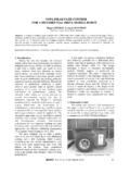
4 B) 3 Nos. MW Gas Turbine generators (GTGs). c) Proposing to add 1 No 18 MW coal based thermal power plant. 2 The single line diagram of the plant is as follows: The major high rating load consist of : a) 2 Nos. MVA rectifier transformers, which are switched ON and OFF on 11 kV bus. b) kV, 730 kW rating induction motor at one of the down stream chemical plant. GENERATOR DIFFERENTIAL PROTECTION : 3 Nos. Gas turbines and 2 Nos. Gas engines are provided with GENERATOR DIFFERENTIAL PROTECTION . A typical case of 1 No. GTG is represented below for case study. FIG. 2 GENERATOR DIFFERENTIAL PROTECTION SCHEME CT SPECIFICATION & SETTING RANGE FIG. 1 PLANT SINGLE LINE DIAGRAM Tested ValuesVk = 275 V; Iex = 10 mAIex at Vk/2 = mAat Vk/4 = mAVendor : ADesign : Vk = 200 V appTested ValuesVk = V.
5 Iex = 75 mAIex at Vk/2 = 14 mAat Vk/4 = mAVendor : BDesign : Vk = 150 V ohms10 Sec400/1 :5P1015 VALOW IMPEDANCE TYPETRANSFORMER DIFFERENTIAL PROTECTIONIpu= Id>= To InSlope1 = 0 50%,Slope2 = 0 100%Turn Point1 = 0 20 In ( Break Point)Id >> = 20 In5thHarmonic Blocking = 10 to 80% Id2ndHarmonic Blocking = 10 to 80% IdCable2 Ifl = 354 ACable1= 100m11 kV SWITCHGEAR 3 GENERATOR DIFFERENTIAL PROTECTION RELAY The GENERATOR DIFFERENTIAL RELAY has following characteristics and the setting range: A multifunction digital three-pole percentage biased DIFFERENTIAL PROTECTION RELAY for transformer or GENERATOR transformer unit is installed wrongly for application of GENERATOR DIFFERENTIAL PROTECTION . The user can select one or more of the functions listed below: a) Absolute value DIFFERENTIAL unit (Ib) b) Percentage biased DIFFERENTIAL unit with two slopes (P1 and P2) c) Over current PROTECTION unit (Id >>) All the above thresh hold values are provided with a time delay of 20 m sec to sec ?
6 ?? (why this is required ?? A wrong concept) The RELAY technical information booklet mentions that activation time of output RELAY is provided to avoid trip commands to switchgear if CT s saturate. Time delay is provided to avoid mal-operation of RELAY due to CT saturation?? Again a wrong concept. RELAY Setting Range : RELAY setting range is as follows: Low Impedance Type Transformer DIFFERENTIAL PROTECTION : Ipu = Id 15% to 200% In, 2nd Harmonic Blocking = 10 to 80% Id Slope 1 = 0 50% 5th Harmonic Blocking = 10 to 80% Id Slope 2 = 0 100% Turn point 1 = 0 20 In Id >> = 20 In The DIFFERENTIAL PROTECTION RELAY tripping Characteristics is as given below: Fig 3: DIFFERENTIAL PROTECTION RELAY Tripping Characteristics 4 Mal-operation of DIFFERENTIAL PROTECTION : DIFFERENTIAL PROTECTION RELAY scheme is stable under steady state operation.
7 The GENERATOR is able to evacuate 100% rated power. However, mal-operation of RELAY is experienced when, a) Switching IN or OFF of MVA rectifier transformer. b) Switching IN of 730 kW induction motor. Event Recording: The mal-operation of this particular PROTECTION was recorded through the history data of corresponding DIFFERENTIAL PROTECTION relays. The details of event recording are as follows: Fig. 4 GTG-1 87G RELAY mal-operation Case : Switching IN of MVA Transformer Rectifier Y phase RELAY is stable because no spill current flows. % Slope ( P1) set at 20%IId I= In ,IId I P1 X IIaIIId I X ( + )2, IId I X I ,Since, Id actual ( ) Operates. 5 B Phase RELAY is stable because no spill current flows. ANALYSIS The above sequence of event recording indicates that under transient condition the current transformers of GENERATOR DIFFERENTIAL PROTECTION are saturating, resulting into unbalance current in the DIFFERENTIAL RELAY operating coil, causing mal-operation of RELAY .
8 The analysis of the PROTECTION scheme confirms that deficiency in CT s Rating Specification. The specification of current transformer installed and commissioned are as follows: Vendor A: Design Value Field Test Values 400/1 CL: 5P10, 20VA Vk = 275 V, Iex = 10 m A Design Vk = 200 V app. Iex at Vk/2 = m A Iex at Vk/4 = m A Vendor B: Design Value Field Test Values 400/1 CL: 5P10, 15VA Vk = V, Iex = 75 m A Design Vk = 150 V app. Iex at Vk/2 = 14 m A Iex at Vk/4 = m A The review of specifications of CT s and field test results indicates that a) Design CT secondary voltages are widely different (200 & 150 V) for either end CT s.
9 B) Tested values of knee point voltage for either end CT s have high difference (275 V & 181 V) for either end CT s. c) In event of external transient load condition the excitation current at Vk/2 or Vk/4 also has a high difference (@ Vk/2, m A & 14 m A, @ Vk/4, A & m A). The above large differences in saturation voltage (Kpv) and excitation current Iex is causing the DIFFERENTIAL current through operating coil and mal-operation of RELAY . 6 Desired specification: The specific requirement for current transformer secondary voltage is worked out as follows: FIG. 5 Actual Requirement of Specification 7 Thus, it is established that due to inadequacy of current transformers rating specification the CTs were saturating resulting into mal-operation of the scheme. Deficiency in RELAY Selection & RELAY Programming: The PROTECTION RELAY installed is a low impedance type, hence, with its bias (slope) characteristics, i) RELAY is less secured ( RELAY operates for spill current flowing through operating coils under transient condition due to CT saturation).
10 Ii) RELAY is not sensitive: Low impedance PROTECTION can be installed, but the RELAY slope characteristics should be with lower bias setting for higher sensitivity. CONCLUSIONS : The above case study confirms that a. It is necessary to provide CTs with adequate CT secondary voltage and specific excitation current to ensure the stability of DIFFERENTIAL PROTECTION CT design shall be as per class: PS specification. b. A low impedance scheme PROTECTION RELAY shall not be preferred for GENERATOR DIFFERENTIAL PROTECTION to ensure i. Higher sensitivity and ii. Higher security against external fault. 8 RECOMMENDATIONS: a) Always use CT s with class: PS specifications for balance current PROTECTION even if relays are provided with feature to detect current transformer saturation and block the RELAY . b) Consider a high impedance DIFFERENTIAL PROTECTION scheme for generators which can provide i) High sensitivity of PROTECTION and ii) High security for external fault and transient disturbances.