Transcription of Genesis LED EGC Series
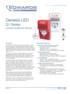
1 08-28-19 Page 1 of 6 DATA SHEET K85001-1021 Not to be used for installation purposes. Issue 1 KIDDE Catalog u Strobes, Horns, Bells, ChimesTechnology that saves livesOverviewGenesis LED EGC Series horns and LED strobes feature a sleek low profile design and energy-efficient technology that makes them less expensive to install and operate by reducing overhead. High performance LEDs require fewer power supplies, backup power, and batteries. These new appliances are designed with, energy-efficiency, and life safety in LED EGC Series uses high efficiency optics, combined with patented electronics, to deliver a highly controlled and efficiently focused light distribution pattern in exchange for lower current requirements. Strobes feature field-selectable 15, 30,75, or 115 cd light with Xenon-type strobes, Genesis LED EGC Series appliances need fewer power supplies and often smaller wire gauge, which lightens conduit requirements.
2 They are also backwards compatible with legacy strobes, so there s no need to replace all your existing devices to upgrade to new LED technology. In fact, EGC strobes can be mixed on the same circuit and used in the same field of view as Xenon-based strobes. This makes Genesis LED EGC Series ideal for new installations and retrofits sound output levels provide the flexibility modern life safety projects demand, while the Genesis LED control protocol keeps multiple strobes on compatible NAC circuits synchronized to well within NFPA 72 requirements. Serviceability is another area where EGC Series appliances shine. The universal room side wiring plate allows for pre-installation and electrical wiring as well as checking continuity with the included diagnostics check bar. EGC Series devices can then be easily snapped into place with the confidence of knowing the wiring is correct. The innovative under-cover diagnostic test points provide easy access to device circuit testing while Features High Performance LED Strobe Technology Ultra low device current consumption allows.
3 More devices per circuit Ability to use lower gauge wire Longer wire runs Fewer booster power supplies High efficiency optics Selectable 15, 30, 75, or 115 cd light output LED devices may be mixed with legacy Xenon strobes Efficient Audible Output Selectable high or low dB horn output Selectable temporal or steady horn output Improved audio frequency range for better wall penetration Low-profile Design protrudes about " from the mounting surface Attractive no visible mounting screws Multiple Marking Options Order Red or White with or without FIRE markings Change markings at any time with replaceablequick-swap covers Easy to Install Pre-install and pre-wire with convenient universal roomside wiring plate Check electrical continuity on room side wiring plate withincluded diagnostics check bar Diagnostics port streamlines device circuit testing Fits 1-gang, 2-gang, 4-inch octagon, and 4-inch squareelectrical boxes Optional red and white trim plates available Slide switches for field configuration 12 to 18 AWG in-out screw terminals for quick wiringGenesis LEDEGC SeriesCeiling Mount Notification DevicesS218, S5389 Page 2 of 6 DATA SHEET K85001-1021 Not to be used for installation purposes.
4 Issue 1+-+-(1) Electrical Box(2) Trim Plate (optional)(3) Wiring plate (required, included with device)(4) Machine screw (2X, supplied with wiring plate)(5) EGC signaling applianceRemoving CoverRemoving DeviceShorting ClipApplicationStrobesGenesis EGC Series strobes are UL 1971-listed for use indoors as ceiling-mounted public-mode notification appliances for the hearing impaired. Prevailing codes require strobes to be used where ambient noise conditions exceed 105 dBA (87 dBA in Canada), where occupants use hearing protection, and in areas of public accommodation as defined in the Americans with Disabilities is important in order to avoid triggering seizures in people with photosensitive epilepsy. All Genesis strobes exceed UL synchronization requirements (within 10 milliseconds over a two-hour period) when used with a synchronization source. See the specifications table for a list of compatible horn output reaches as high as 92 dBA and features an improved audio frequency range compared with other Genesis horns.
5 This results in excellent sound penetration through walls and a clear warning of danger. Horn only models may be configured for either coded or non-coded notification appliance circuits. They can also be set for high or low dBA output. This setting reduces horn output by about 6 suggested sound pressure level for each signaling zone used with alarm signals is at least 15 dBA above the average ambient sound level, or 5 dBA above the maximum sound level having a duration of at least 60 seconds, whichever is greater. These values are measured at five feet ( m) above the floor. The average ambient sound level is A-weighted, fast response sound pressure measured over a 24-hour the distance from the signal to the ear will theoretically result in a 6 dBA reduction of the received sound pressure level. The actual effect depends on the acoustic environment in the space. A 3 dBA difference represents a barely noticeable change in EGC horns and strobes mount to the required GP10 room side wiring plate.
6 The GP10 mounting plate is included with the device for convenient pre-installing and pre-wiring. The device can be removed easily from the room side wiring plate by pushing up with a screwdriver. The cover can also be removed from the device easily with a screwdriver to access the light and sound output settings and a diagnostics test port for voltage LED EGC Series horns, strobes, and horn-strobes mount to any standard one-gang, two-gang, 4-inch octagon, and 4-inch square electrical box. Matching optional EGCT trim rings are available to cover oversized openings. Optional color matched double-gang surface boxes are also available. Genesis LED EGC Series are listed to be both wall mounted or ceiling circuit outHorn/strobe circuit in (signal polarity shown in the active condition) (1)(2)(3)(4)(5) Page 3 of 6 DATA SHEET K85001-1021 Not to be used for installation purposes. Issue 1 Field ConfigurationTemporal horn and horn-strobe models are factory set to sound in a three-pulse temporal pattern.
7 By sliding the tone selector switch, horn only models may be configured for constant horn output that can be coded at precise intervals by KIDDE control panels and control : Temporal 3 coding is the required output for fire notification devices per NFPA 72. Any device coding other than temporal 3 is at the discretion and approval of the local authority having jurisdiction (AHJ).Horns and horn-strobes are factory set for high dB output. Low dB output may be selected by sliding the tone selector switch. This reduces the output by about 6 LED clear strobes and horn-strobes may be set for 15, 30, 75, or 115 candela output. The output setting is changed by simply removing the cover and sliding the candela switch to the desired setting. The device does not have to be removed from the wall to change the output setting. The setting remains visible through a small window on the device after the cover is closed. DimensionsEGC Notification AppliancesDiagnosticsTest points indicated above are used to validate the Notification Appliance Circuit and verify device Trim Plate (optional)Light and Sound Output SettingsHornsSound setting16 to 33 VDC16 to 33 VFWRC-Low, T-Low 20 mA25 mAC-High, T-High30 mA40 mAHorn-StrobesStrobe settingSound setting16 to 33 VDC16 to 33 VFWR15, 30, 75, 115C-Low, T-Low50 mA60 mAC-High, T-High60 mA75 mAStrobesStrobe setting16 to 33 VDC16 to 33 VFWR15, 30, 75, 11535 mA45 mAOperating current ( cm) ( cm) (5)(6)(7)(8)(1)(2)(3)(4)(1) Constant, low dB(2) Constant, high dB(3) T3 temporal, low dB(4) T3 temporal, high dB(5) 115 candela(6) 75 candela(7) 30 candela(8) 15 candela ( cm) ( cm)Page 4 of 6 DATA SHEET K85001-1021 Not to be used for installation purposes.
8 Issue 1 SpecificationsOperating voltage16 to 33 VDC, 16 to 33 VFWRHorn signal typeConstant or TC3 temporalLight output15, 30, 75, or 115 candelaStrobe flash rate1 fps (flash per second) max. between any two devices. To determine allowed wire resistance, refer to these specifications, and the specifications for the synchronized signal SourcesKidde CC Series Signal Modules, booster and Auxiliary Power Supplies, Intelligent and Conventional Control PanelsWire size12 to 18 AWG ( to mm2)MountingWall or Ceiling mountDimensions ( D) in. ( cm)Strobe-to-box center inches ( cm)Compatible electrical boxes [1]1-gang, 2-gang, 4-inch octagon, 4-inch squareTrim platesEGCTR, EGCTW in. ( cm)Operating environment Temperature Relative humidity 32 to 122 F (0 to 50 C) 0 to 93% noncondensingStorage Temperature-40 to 158 F (-40 to 70 C)[1] Electrical boxes must be at least 1-1/2 in. ( cm) DistributionSound OutputHorn & Horn-StrobeSound settingReverberant (UL464)Anechoic (CAN/ULC - 5925)C-Low, T-Low 80 dBA86 dBAC-High, T-High86 dBA92 dBASound pattern Horn Models (ULC)AxisAngle ( )Output (dBA)Horizontal115 and Vertical125 and pattern Horn-Strobe Models (ULC)AxisAngle ( )Output (dBA)Horizontal145 and 155 and and and LeftHorizontal RightVertical BottomMeasuredUL Minumum 0501001502002500510152025303540455055606 5707580859085807570656055504540353025201 5105051015202530354045505560657075808590 858075706560555045403530252015105 Page 5 of 6 DATA SHEET K85001-1021 Not to be used for installation purposes.
9 Issue 1 Notification AppliancesColorMarkingHornsEGCARFRedFIRE EGCAWFW hiteFIRES trobesEGCVRFRedFIREEGCVRNRedNoneEGCVWFW hiteFIREEGCVWNW hiteNoneHorn-strobesEGCAVRFRedFIREEGCAVR NRedNoneEGCAVWFW hiteFIREEGCAVWNW hiteNoneReplacement Appliance CoversColorMarkingHorn CoversEGCARF-CVRRedFIREEGCAWA-CVRW hiteALERTEGCAWF-CVRW hiteFIREEGCAWN-CVRW hiteNoneStrobe CoversEGCVRF-CVRRedFIREEGCVWA-CVRW hiteALERTEGCVWF-CVRW hiteFIREEGCVWN-CVRW hiteNoneHorn-strobe CoversEGCAVRF-CVRRedFIREEGCAVWA-CVRW hiteALERTEGCAVWF-CVRW hiteFIREEGCAVWN-CVRW hiteNoneOrdering InformationAccessoriesGP10 Room Side Wiring Plate (required, included with device)EGCTRTrim plate, EGC Series , redEGCTWTrim plate, EGC Series , white27193-21 Two-gang surface mount box, red27193-26 Two-gang surface mount box, whiteModel Number Syntax, AppliancesModel Number Syntax, Replacement CoversEGCAVRFH ousing ColorR = RedW = WhiteHousing MarkingN = NoneF = FIREF unctionsA = Horn onlyV = Strobe onlyAV = Horn-StrobeGenesis SeriesEGC = Ceiling mount appliancesEGCAVRF-CVRH ousing ColorR = RedW = WhiteHousing MarkingN = NoneF = FIREA = ALERTF unctionsA = Horn onlyV = Strobe onlyAV = Horn-StrobeGenesis SeriesEGC = Ceiling mount appliancesCover DesignationPage 6 of 6 DATA SHEET K85001-1021 Not to be used for installation purposes.
10 Issue 1 Technology that saves livesContact : Corporate Park Drive Mebane, NC 27302 Kidde is a registered mark in the United States and other countries. 2019 Walter Kidde Portable Equipment. All rights