Transcription of GenICam Standard - EMVA
1 Version Standard Page 1 of 57 GenICam Standard Generic Interface for Cameras Version Version Standard Page 2 of 57 Table of Contents 1 5 2 GENAPI MODULE CONFIGURING THE CAMERA .. 7 INTRODUCTION .. 7 BASIC STRUCTURE OF THE CAMERA DESCRIPTION FILE .. 8 NODES, INTERFACES, AND ABSTRACT FEATURES .. 10 GETTING AND SETTING VALUES .. 11 ACCESS MODE .. 12 CACHING .. 16 IDENTIFYING AND VERSIONING A CAMERA DESCRIPTION FILE .. 20 Versioning the Schema .. 21 Versioning the Camera Description File .. 21 Identifying and Caching the Camera Description File .. 22 AVAILABLE NODE TYPES .. 22 Node .. 22 Category .. 25 Register .. 27 Arrays and Selectors .. 29 Integer, IntReg, MaskedIntReg .. 30 StructReg .. 33 Boolean.
2 34 Command .. 35 Float, FloatReg .. 35 Enumeration, EnumEntry .. 36 StringReg .. 38 String ( ) .. 38 SwissKnife, IntSwissKnife, Converter, and IntConverter .. 38 ConfRom, TextDesc, and IntKey .. 41 DcamLock and SmartFeature .. 42 Port .. 43 Group element .. 44 AVAILABLE INTERFACES .. 45 IInteger Interface .. 45 IFloat Interface .. 45 IString Interface .. 46 IEnumeration Interface .. 46 ICommand Interface .. 46 IBoolean Interface .. 46 IRegister Interface .. 46 ICategory Interface .. 47 IPort Interface .. 47 ISelector Interface .. 47 3 48 Version Standard Page 3 of 57 ENDIANESS OF GIGE VISION CAMERAS .. 48 Behavior of products based on schema version and newer .. 48 Behavior of products based on schema version .. 49 Passing the schema version to the IPort implementation.
3 49 DEFAULT VALUES OF OPTIONAL NODE ELEMENTS AND ATTRIBUTES .. 50 4 ACKNOWLEDGEMENTS .. 54 5 RIGHTS AND TRADEMARKS .. 54 6 INDEX .. 55 Version Standard Page 4 of 57 HISTORY Version Date Changed by Change Fritz Dierks, Basler Released version as voted on during the Montreal meeting draft 1 Fritz Dierks, Basler First draft for version Fritz Dierks, Basler Released Fritz Dierks, Basler Fixed some minor miss-spellings and added some clarifications Fritz Dierks, Basler Rene Weber, Baumer - Added a description of default values which are either already given in the schema or in the reference implementation - Added ValidValueSet - Added clarifications provided by Eric Bourbonnais, Dalsa Fritz Dierks, Basler Mattias Josefsson, Sick - Fixed several typos Version Standard Page 5 of 57 1 Overview Today s digital cameras are packed with much more functionality than just delivering an image.
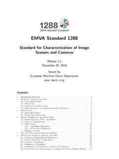
4 Processing the image and appending the results to the image data stream, controlling external hardware, and doing the real-time part of the application have become common tasks for machine vision cameras. As a result, the programming interface for cameras has become more and more complex. The goal of GenICam is to provide a generic programming interface for all kinds of cameras. No matter what interface technology the cameras are using or what features they are implementing, the application programming interface (API) should be always the same (see Figure 1). Figure 1 The GenICam vision The GenICam Standard consists of multiple modules according to the main tasks to be solved: GenApi : Application programming interface (API) for configuring a camera GenTL : API for transport layer (TL) that allows grabbing images SFNC : Standard Feature Naming Convention CLProtocol : API for interfacing Camera Link camera to GenAPI.
5 Smart Cameras GigE 1394 Camera Link Smart Cameras GigE 1394 Camera Link Unified API Version Standard Page 6 of 57 GenCP : Generic Control Protocol Modules can be released independently from each other. Version Standard Page 7 of 57 2 GenApi Module Configuring the Camera Introduction The GenApi module deals with the problem of how to configure a camera. The key idea is to make camera manufacturers provide machine readable versions of the manuals for their cameras. These camera description files contain all of the required information to automatically map a camera s features to its registers. A typical feature would be the camera s gain and the user s attempt might be, for example, to set Gain=42. Using GenICam , a piece of generic software will be able to read the camera s description file and figure out that setting the Gain to 42 means writing a value of 0x2A to a register located at 0x0815.
6 Other tasks involved might be to check in advance whether the camera possesses a Gain feature and to check whether the new value is consistent with the allowed Gain range. Note that adding a new feature to a camera just means extending the camera s description file, thus making the new feature immediately available to all GenICam aware applications. ApplicationGenApiTransportLayer CameraCamera APIT ransport Layer APIC amera Register Interface Figure 2 Layers for accessing a camera Figure 2 shows the layers involved in configuring a camera. The application requires a camera API that allows dealing with the camera s features, for example, by writing code which looks like this: = 42; The GenApi module will translate this call into a series of calls to register access functions provided by the transport layer API, for example, like this: ( 0x0815, 0x2A, 2 ); // address, data, length Version Standard Page 8 of 57 Finally, the transport layer will deliver the calls to the camera interface.
7 GenApi currently assumes that the camera is configured using a flat register space. The GenICam Standard defines the syntax of the camera description file plus the semantics of the transport layer API. In addition, the GenICam Standard recommends but does not enforce the usage of certain names and types for common features such as Gain or Shutter. The Standard does not contain the actual code for reading the description file and translating features to registers, nor does it contain the transport layer code. Everyone is free to do their own implementation. There is, however, a reference implementation available that can be freely used. Note that the GenApi section in this document deals with the camera description file only. It is intended to help the GenICam user to understand the key ideas behind the GenApi module and to enable people to write their own camera description files.
8 The GenApi reference implementation comes with a reference manual showing how an end user can use the GenApi module even without a deeper understanding of the concepts laid out in this section. Basic Structure of the Camera Description File The camera is described by means on an XML file containing a set of nodes with each node having a type and a unique name. Nodes can link to each other and each connection plays a certain role. Figure 3 shows a very simple example in graphical notation. The nodes are shown as bubbles labeled "type::name," and the links are shown as arrows labeled with the role name. There are two special nodes: the Root node from which one can start walking the node graph and the Device node that provides the connection to the transport Figure 3 Topology of a graph constructed from a simple configuration file 1 Note that GenApi can be used to access other register based devices in addition to cameras.
9 Version Standard Page 9 of 57 The Gain node in Figure 3 is of the IntReg type, which allows the extraction an integer from a register. Looked at from the Root node, it is a feature of the camera. The Root node, therefore, contains a link named pFeature referencing the Gain node. To read and write the Gain registers, the Gain node needs access to the camera port, and thus it contains a link to the Device node. The link is named pPort and references the Device node. The Gain node contains all of the information required to extract a two byte unsigned integer in BigEndian mode. The complete camera description file looks like this: <?xml version=" " encoding="utf-8"?> <RegisterDescription ModelName="Example01" VendorName="Test" ToolTip="Example 01 from the GenApi Standard " StandardNameSpace="None" SchemaMajorVersion="1" SchemaMinorVersion="1" SchemaSubMinorVersion="0" MajorVersion="1" MinorVersion="0" SubMinorVersion="0" ProductGuid="1F3C6A72-7842-4edd-9130-E2E 90A2058BA" VersionGuid="7645D2A1-A41E-4ac6-B486-153 1FB7 BECE6" xmlns=" " xmlns:xsi=" " xsi.
10 SchemaLocation=" "> <Category Name="Root"> <ToolTip>Entry for traversing the node graph</ToolTip> <pFeature>Gain</pFeature> </Category> <IntReg Name="Gain"> <ToolTip>Access node for the camera's Gain feature</ToolTip> <Address>0x0815</Address> <Length>2</Length> <AccessMode>RW</AccessMode> <pPort>Device</pPort> <Sign>Unsigned</Sign> <Endianess>BigEndian</Endianess> </IntReg> <Port Name="Device"> <ToolTip> Port node giving access to the camera</ToolTip> </Port> </RegisterDescription> The <?xml> node is a processing element giving hints about the encoding of the file and is always the same. The <RegisterDescription> element is the outermost bracket encapsulating all nodes of the camera. The camera is identified by the ModelName and VendorName attributes (model Version Standard Page 10 of 57 Example01 from vendor Test in this case).