Transcription of GERMANY TOWNSHIP CONSTRUCTION …
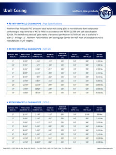
1 1 GERMANY TOWNSHIP CONSTRUCTION standards and material SPECIFICATIONS for WELLS & GEOTHERMAL SYSTEMS I. well CONSTRUCTION REQUIREMENTS 1. casing . All domestic, agricultural, irrigation, commercial, and industrial wells used for supplying water, monitoring water levels, or geothermal systems shall be equipped with watertight and durable casing constructed of listed material and minimum wall thickness: Wrought iron - inches ( mm) Steel - inches ( mm) Polyvinyl chloride (PVC) plastic inches ( mm) PVC Monitoring wells inches ( mm) A. Joining. The sections of casing shall be joined together by threaded couplings, or full circumferential welding for ferrous materials, and threaded couplings or solvent welding in accordance with ANSI/NSF Standard 14 for PVC. Other nonferrous casing joining must meet AWWA Standard A100. B. Minimum depth. The casing shall be carried at least 10 feet (3048mm) into competent bedrock to a minimum depth of 20 feet (6096 mm).
2 C. Grouting. casing shall be grouted in place and grouting must be compatible with casing material . D. Minimum borehole diameter. The borehole shall be 3 inches ( mm) larger in diameter than the outside diameter of casing to allow for a minimum of 1-1/2 inches ( mm) of annular space for grout placement. E. Minimum extension above grade. casing shall extend at least 12 inches ( mm) above ground surface. The casing may be terminated at grade or just below grade if fitted with a waterproof and airtight cap and is located within a box-type enclosure with an access lid such as a small 2 meter vault. F. Ferrous casing . Ferrous casing shall be new pipe meeting ASTM or API specifications for water supply well CONSTRUCTION . It shall be equipped with a drive shoe or other effective casing seal and have full circumference welds or threaded pipe joints. G. Non-ferrous casing . Non-Ferrous casing shall meet appropriate ANSI, ASTM or NSF standards for water well casing applications.
3 It shall not be driven. 2. Grouting. The annular space between the well casing and the earth formation shall be completely filled with approved grout from the bottom of the annular space outside the casing to grade or from a minimum depth of 20 feet (6096mm) to grade in one continuous operation within 7 days of completion of drilling. In the event that grouting is done following completion of all drilling operations, all obstructions must be completely cleared prior to placement of grout material . A. Approved Grout: Approved grout shall be mixed and applied according to manufacturer s specifications ( , water content and viscosity) for use in grouting wells and/or geothermal boreholes. The following types of grouting are specifically authorized: a) Neat Cement Grout: A fluid mixture of hydraulic cement and water, with or without admixtures in the following proportions; one bag of cement (94 pounds ( kg) to not less than 5 gallons ( l) nor more than 7 gallons ( l) of water.
4 B) Thermally Enhanced Bentonite Based Grout: Thermally-enhanced bentonite based grout is a high solids mixture of sodium bentonite, inert additives such as sand or rock dust that enhance thermal conductivity, and potable water mixed according to the manufacturer's specifications. The sand must be clean so as to not introduce contaminants into the grout mixture. The use of special additives to alter permeability, increase thermal conductivity, increase fluidity, control grout loss, and/or control time of set, and the composition of the resultant slurry, must be used in accordance with the manufacturer's specifications. c) Bentonite Based Grout: Bentonite based grout is a high solids mixture of sodium bentonite and a pumping additive that provides a simple, economical method to seal annular spaces around well 3 casings and grout geothermal boreholes. The slurry develops a high quality grout with low permeability. The use of these two items must be used in accordance with the manufacturer's specifications.
5 B. Tremie Placement Method for Grout. After water or other drilling fluid has been circulated in the annular space sufficient to clear obstructions, grout shall be placed by pressure pumping through a tremie pipe. The tremie pipe shall be lowered to the bottom of the zone being grouted, and raised slowly as the material is introduced. C. Other Fill and Bridging Materials. If the entire annular space cannot be filled with approved grout (below the minimum 20 feet), other fill or bridging materials may be used. Acceptable fill materials are site specific and may include, but may not be limited to: bentonite chips or pellets, clean cuttings removed from the borehole; clean sand, gravel, or a mixture of sand and gravel; and/or cement and water or concrete mixes. (a) Tremie Placement Method for Fill and Bridging Materials: The tremie pipe shall be lowered to the bottom of the zone being filled, and raised slowly as the fill material is introduced.
6 When using the tremie pipe method to install fills, the bottom of the tremie shall be maintained as close as possible to, but not inside of, the emplaced fill. D. Pitless adaptor. During the installation of a pitless adaptor, grout material may be removed from the exterior of the casing in order to provide a watertight seal between the casing and this adaptor. The pitless adaptor must be installed at least 3 feet ( mm) below grade and include conduits, stone, dust or sand. E. Geothermal. Geothermal system vertical boreholes containing loop pipes may be filled with approved grout to the total depth. These boreholes must be filled with only approved grout from a minimum depth of 20 feet (6096 mm) below grade up to the ground surface. F. Direct Exchange (DX) Geothermal. This type of geothermal system must use a cement-based, special grout in the boreholes and must have electronic corrosion protection for the metal piping.
7 3. Packer. Packers when used shall be of material that will not impart adverse taste, odor, toxic substances or bacterial contamination to the well water. 4 4. Pitless installations. Pitless installations are those where the casing terminates above the ground surface or below grade as specified above. Where used, they shall be effectively sealed. All buried suction lines shall be encased. The access casing shall be protected against corrosion and shall extend at least 12 inches ( mm) above the natural ground surface and to a depth of at least 20 feet (6096 mm) below the ground surface. Pitless adaptors shall not be installed through a ferrous casing by cutting the hole with a torch or flame, but must be installed by using a hole saw or drill to make the hole through the ferrous casing . 5. well screens. When needed, well screens shall provide maximum amount of open area while still maintaining structural strength. They shall have the size of openings based on an analysis to preclude entry by sand, silt, and other undesirable elements.
8 6. well cap. All wells shall be installed with a sanitary well cap to prevent any surface pollutants from entering the well or any vandalism to the well or aquifer. In the event of a flowing well , the well cap must stop overflow from the well with an artesian well cap. casing terminated at grade or just below grade, shall have a waterproof and airtight well cap installed. 7. Outdoor Venting. Where outdoor venting is required, an overlapping cover or pipe with an opening facing downward shall be required. In no case shall openings be less than 12 inches ( mm) above the ground. Vent shall be screened and any other cracks or holes must be sealed with caulk to prevent insect entry. 8. Geothermal. Geothermal installations shall be designed and constructed to provide an effective watertight seal with the well casing or water storage reservoir and to prevent contamination from reaching the water chamber or interior pump surfaces 9.
9 Turbine pump installation. The suction opening shall be located at a sufficient distance from the bottom of the well so as to prevent agitation of accumulated sediment. The suction opening shall be placed at least 2 feet ( mm) below the maximum drawdown of the water in the well . A turban pump base installed directly over a well casing or pipe sleeve shall be designed to provide a watertight seal. It must be mounted above the 100-year flood elevation. Consideration shall be taken for the convenient access, removal, maintenance and repair of the pump and related equipment. 10. Disinfection. Following completion of CONSTRUCTION , well must be disinfected. The well shall be pumped continuously until the water discharge is clear. It shall be filled with water containing concentration of not less than 100 parts per million of free chlorine. A portion of this solution shall be recirculated directly to 5 the well in order to insure proper agitation.
10 The water shall not be used for a period of 24 hours. Disposal of the purged water shall be at a point so as to minimize adverse effects to aquatic life and in no way directed into any subsurface sewage disposal system. 1 ounce ( ml) of dry calcium hypochlorite dissolved in gallons ( ) of water makes the proper strength disinfectant solution. Household bleach may be used for disinfection as given in Table 1. Table 1 Volume of Chlorine Bleach for Shock Chlorination of Wells and Springs Water Depth well Diameter 6 in ( mm) 8 in ( mm) 10 in (254 mm) 24 in ( mm) 32 ( mm) 36 in ( mm) 10 ft ( m) 1 c ( ml) 1 c ( ml) 2 c ( ml) 12 c (2839 ml) 16 c (3785 ml) 24 c (5678 ml) 20 ft ( m) 1 c ( ml) 2 c ( ml) 4 c ( ml) 20 c (4732 ml) 32 c (7571 ml) 40 c (9464 ml) 30 ft ( m) 2 c ( ml) 4 c ( ml) 6 c (1420 ml) 40 ft ( m) 2 c ( ml) 4 c ( ml) 8 c (1893 ml) 60 ft ( m) 4 c ( ml) 6 c (1420 ml) 12 c (2839 ml) 80 ft ( m) 4 c ( ml) 8 c (1893 ml) 14 c (3312 ml) 100 ft ( m) 6 c (1420 ml) 10 c (2366 ml) 16 c (3785 ml) 150 ft ( m) 10 c (2366 ml) 16 c (3785 ml) Cup = 8 liquid ounces 11.